737 Flight Crew Operations Manual
Electrical -
System Description
Boeing Proprietary. Copyright © Boeing. May be subject to export restrictions under EAR. See title page for details.
D6-27370-866-EGP 6.20.5
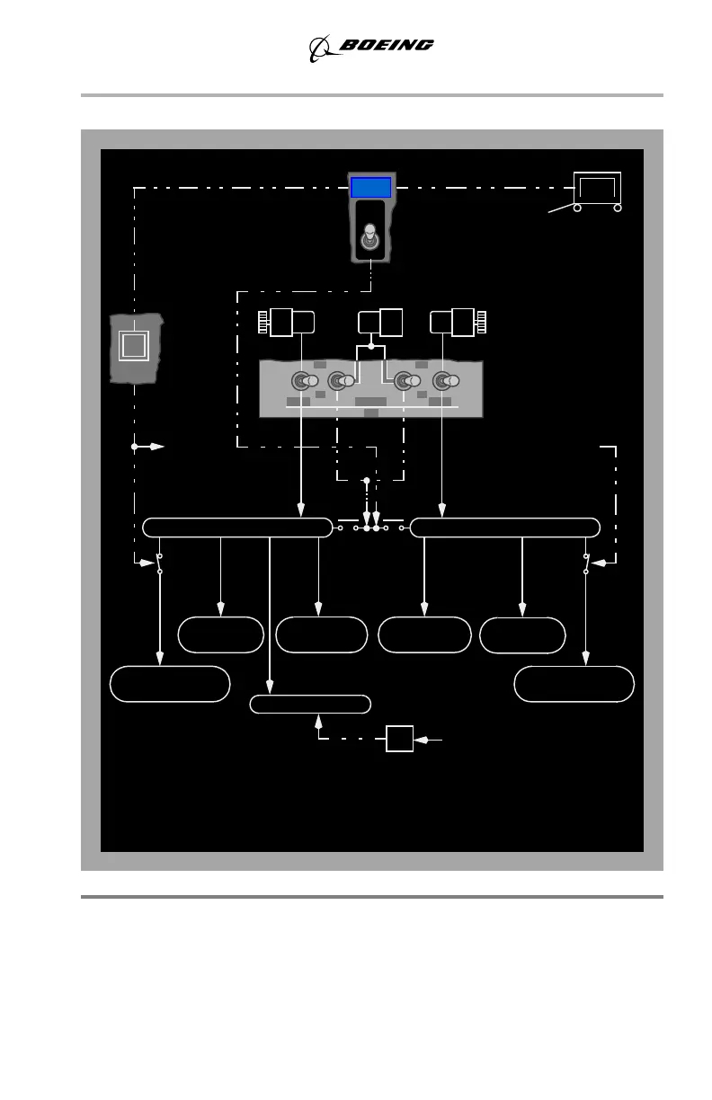
AC Power Schematic
Electrical Power Controls and Monitoring
Generator Drive
The IDGs contain the generator and drive in a common housing, and are lubricated
and cooled by a self–contained oil system. An integral electro–mechanical
disconnect device provides for complete mechanical isolation of the IDG.
GEN 2
ON
APU GENGEN 1
RELAY
SERVICE
GND
RELAY
SERVICE
GND
PWR
OFF
GRD
ON
GRD POWER
AVAILABLE
DRIVE
GEN
DRIVE
GEN
OFF
ON
OFF
APU
GEN
1
GEN
2
GEN
APU
STANDBY POWER SWITCH - AUTO
BATTERY SWITCH - ON
BUS TRANSFER SWITCH - AUTO
ENGINE GENERATOR CONNECTED TO RELATED BUS
AIRPLANE CONFIGURATION:
GROUND
SERVICE
TO GND
SVC SWITCH
FROM GND
SVC BUS 2
SERVICE BUS 2
115V AC GND
115V AC
MAIN BUS 2
BUS A & B
GALLEY
BUS C & D
GALLEY
115V AC GND
SERVICE BUS 1
MAIN BUS 1
115V AC
AC TRANSFER BUS 2AC TRANSFER BUS 1
AC STANDBY BUS
INV
FROM BAT/BAT CHG
BTB1
BTB2
May 15, 2008