737 Flight Crew Operations Manual
Anti-Ice, Rain -
Controls and Indicators
Boeing Proprietary. Copyright © Boeing. May be subject to export restrictions under EAR. See title page for details.
3.10.4 D6-27370-866-EGP
AUTO – power is automatically supplied to both A and B probe heat systems
when either engine is running.
3 TAT TEST Switch
Push - Electrical power applied to TEMP PROBE on the ground.
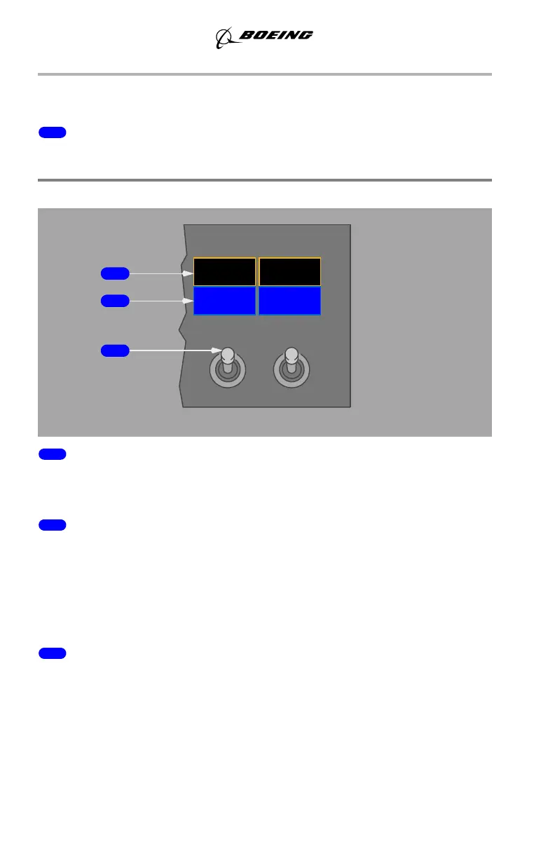
Engine Anti–Ice Panel
1 COWL ANTI–ICE Lights
Illuminated (amber) – indicates an overpressure condition in duct downstream of
engine cowl anti–ice valve.
2 COWL VALVE OPEN Lights
Illuminated (blue) –
• bright – related cowl anti–ice valve is in transit, or, cowl anti–ice valve
position disagrees with related ENGINE ANTI–ICE switch position
• dim – related cowl anti–ice valve is open (switch ON).
Extinguished – related cowl anti–ice valve is closed (switch OFF).
3 ENGINE ANTI–ICE Switches
ON –
• related engine anti–ice valve is open
• stick shaker logic is set for icing conditions.
OFF –
• related engine anti–ice valve is closed
• stick shaker logic returns to normal if wing anti–ice has not been used in
flight.
1
ON
OFF
COWL
COWL VALVE
ENG
ANTI-ICE
2
OPEN
COWL
ANTI-ICE
ANTI-ICE
COWL VALVE
OPEN
FORWARD OVERHEAD PANEL
1
2
3
March 31, 2016