Chery QQ Service Manual BCM Computer Control System
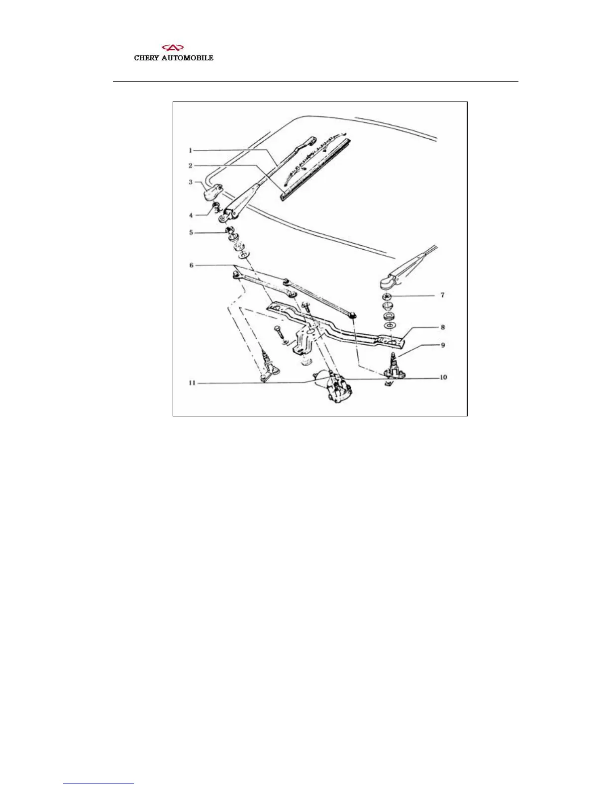
Structure of the wiper
1- wiper arm 2- wiper rubber strip 3- protective cover
4、5、7- nuts 6- swing link 8-
abutment 9- journal
10- motor 11- crankshaft
The circuit system for the wiper and wash equipment is shown in the figure. If the
start-up switch is turned on, by switching the wiper switch between the positions thereof,
the power supply controlled by the start-up switch can be connected directly to the wiper
motor through the fuse (fast position) or can actuate the motor through the relay (slow
position, intermittent position and water injection position).
When the wiper switch is in its lowest position, the wiper is out of operation. When the
wiper switch is turned to the “2” position, the wiper operates in intermittent mode. Every
some 6 seconds the wiper does one operating cycle. When the wiper switch is turned in
the direction of the steering wheel, the front wiper is actuated, the water injection pump
pumps water, the wiper moves to and fro for 3 to 4 times and stops. When the wiper
- 100 -