Chery QQ Service Manual Transmission System
F
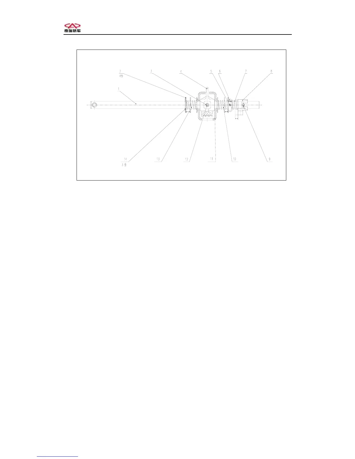
Fig.3-44 Shift and select lever shaft assembly
1- Shift and select lever shaft 2- Gasket 3- Slotted spring pin
4- Select lever shaft 5- Slotted spring pin 6- Spring
7- Shift cam spring 8- Shift cam 9- Slotted spring pin
10- Return spring 11- Interlock 12- Slotted spring pin
13- Return spring 14-E- snap ring
1.Use the professional tools to remove the 4 pin, 3 E- snap ring and component
from the select lever shaft.
2. Clear up all the parts, if necessary, please replace the used parts.
3. Install according to the reverse process.
Notice:
When hammering the slotted spring pin, use the wood block to support to
prevent bending the shift and select lever shaft.
When installing reverse, 5th interlock roller, first enlace the cam return
spring, secondly hammer the slotted spring pin.
Keep the identical directions of the select lever shaft, reverse, 5th shift cam
and spring.
1st, 2nd shift fork shaft assembly and 3rd, 4th Shift fork shaft assembly.
-74-
Chery Automobile Co., Ltd