AH500 Hardware and Operation Manual
2-18
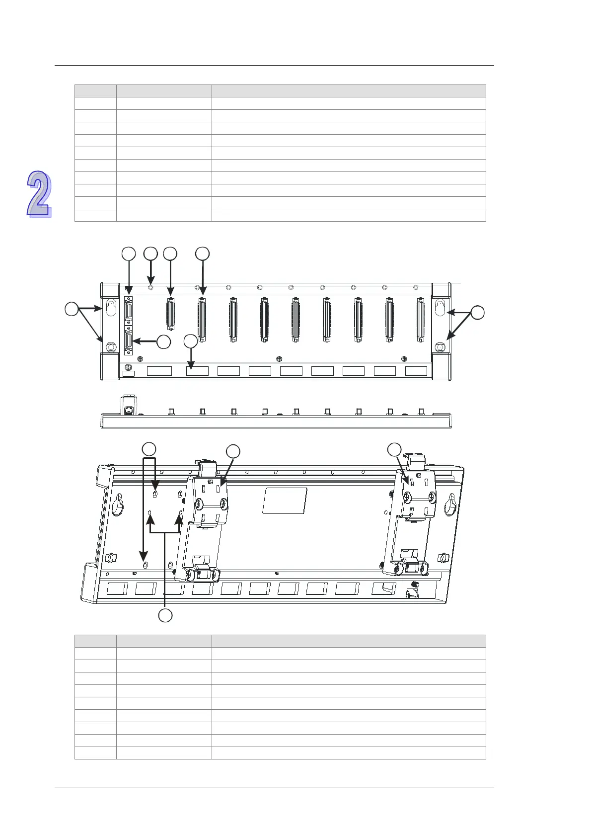
It is connected to an inferior backplane.
After a module is installed, it is fixed by a screw.
Connecting the backplane and a power supply module
Connecting the backplane and a CPU module
Connecting the backplane and an input/output module
The projection under a module is inserted into this hole.
Hanging a backplane on a DIN rail
After a mounting clip is installed, it is fixed by screws.
A mounting clip is pressed into these locating holes.
Profile of the extension backplane AHBP08E1-5A
It is connected to a superior backplane.
It is connected to an inferior backplane.
Connecting the backplane and a power supply module
Connecting the backplane and an input/output module
After a module is installed, it is fixed by a screw.
The projection under a module is inserted into this hole.
Hanging a backplane on a DIN rail
After a mounting clip is installed, it is fixed by screws.

 Loading...


