F 32 17
A
Locking pin (C) must be raised for adjustment.
- Check the adjustment constantly: Switch the conveyor on and observe the scraper
from a safe distance.
Ensure:
- that all scraper blades move forwards and backwards evenly
- that all scraper blades have contact with the conveyor belt at the same time
- If necessary, switch the conveyor off and retighten the scraper evenly in steps of
1 to 2 turns (T-bolts (A))!
- Repeat process until correct setting is achieved.
A
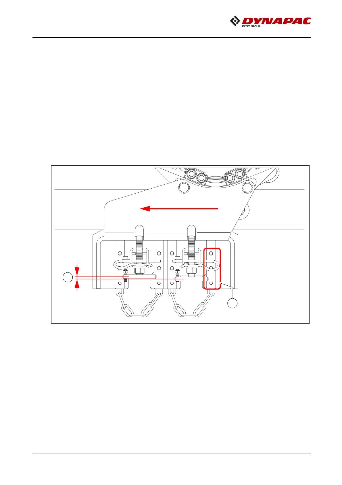
The following drawing shows a typical adjustment.
The distance between the lower edge of the guide plate and the visible ends of the
bolt (D) acts as guidance.
A
The depicted adjustment serves as an indicative value: the position of the scrapers
can vary by a few millimetres, depending on
- conveyor belt tension (pay attention to correct adjustment!)
- scraper wear
- production tolerance
A
The front scraper in the travel direction is at a greater distance from the deflection axle
and is therefore always higher (E) than the rear scraper.