EasyManuals Logo

GE LOGIQ P9 Service Manual

GE LOGIQ P9
602 pages
To Next Page IconTo Next Page
To Previous Page IconTo Previous Page
Page #420 background imageLoading...
Page #420 background image
GERAFT LOGIQ P9/P7
D
IRECTION 5604324, REVISION 11 DRAFT (JANUARY 24, 2019) SERVICE MANUAL
8-94 Section 8-14 - Replacement of OPIO and Related Parts
4) Remove 10 screws on BRKT and remove 1 BRKT Refer to following figure.
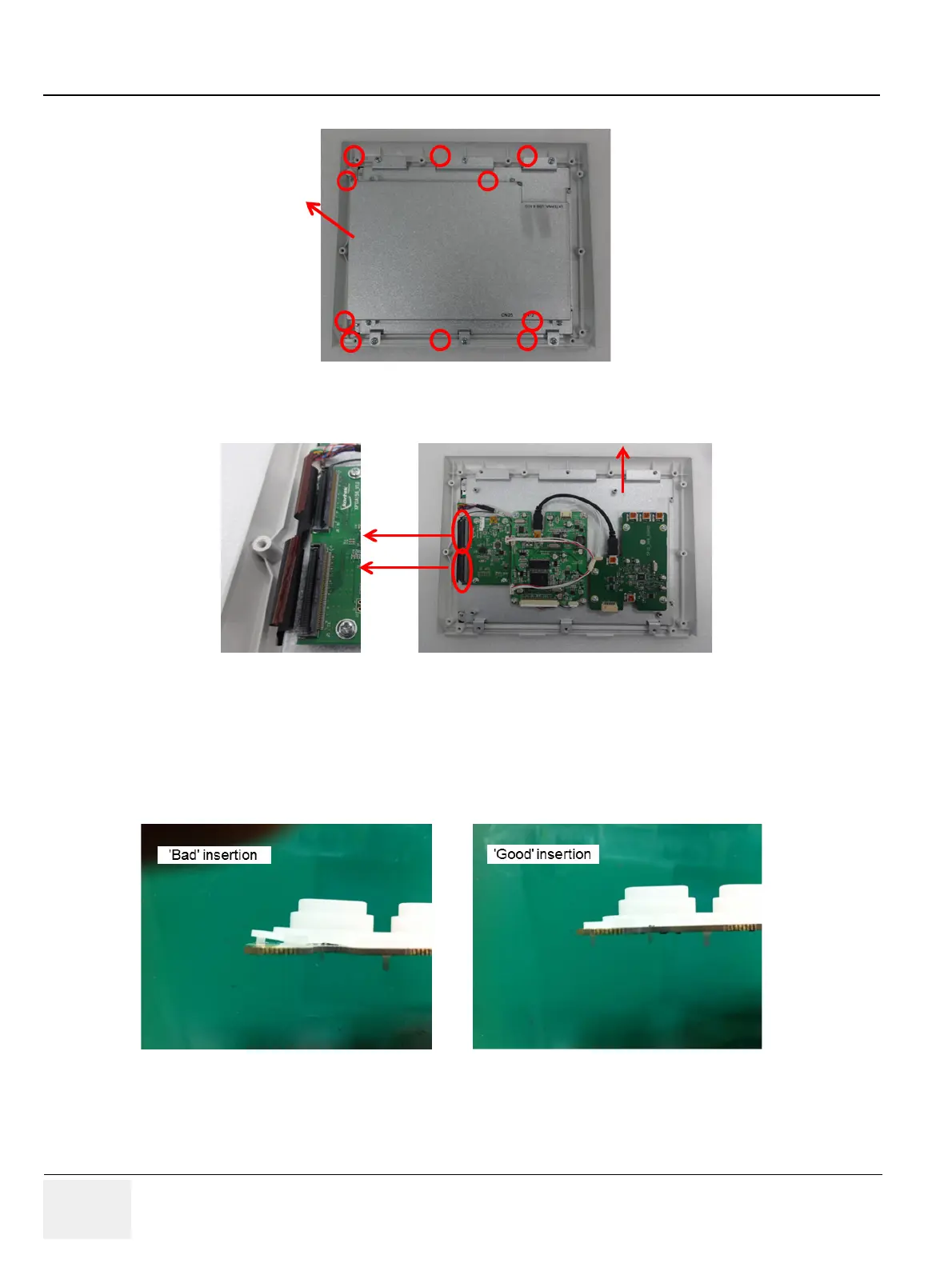
Figure 8-95 Screw points to remove 3 BRKT
5) Remove flexible connectors and carefully lift up Touch panel.
Figure 8-96 Disconnection of Touch panel connector
8-14-4 Installation Procedure
1) Parts to be installed in reverse order of removal.
NOTE: Make sure to assemble “Rubber Sheet” securely to PWA.
Figure 8-97 Installation of PWA

Table of Contents

Other manuals for GE LOGIQ P9

Questions and Answers:

Question and Answer IconNeed help?

Do you have a question about the GE LOGIQ P9 and is the answer not in the manual?

GE LOGIQ P9 Specifications

General IconGeneral
TypeUltrasound System
3D/4D ImagingYes
ElastographyYes
ConnectivityDICOM, USB, Ethernet, HDMI
Doppler ModesColor Doppler, Power Doppler
Probesconvex, linear, phased array
Imaging ModesM-Mode, Color Doppler, Power Doppler
PortabilityCart-based
ApplicationsVascular, Cardiac, OB/GYN, Musculoskeletal
WeightApprox. 80 kg
Touch Panel10.1-in touchscreen

Related product manuals