EasyManuals Logo

GE LOGIQ P9 Service Manual

GE LOGIQ P9
602 pages
To Next Page IconTo Next Page
To Previous Page IconTo Previous Page
Page #412 background imageLoading...
Page #412 background image
GERAFT LOGIQ P9/P7
D
IRECTION 5604324, REVISION 11 DRAFT (JANUARY 24, 2019) SERVICE MANUAL
8-86 Section 8-14 - Replacement of OPIO and Related Parts
8-14-3-3 Removal Procedure - AN Keyboard (Option)
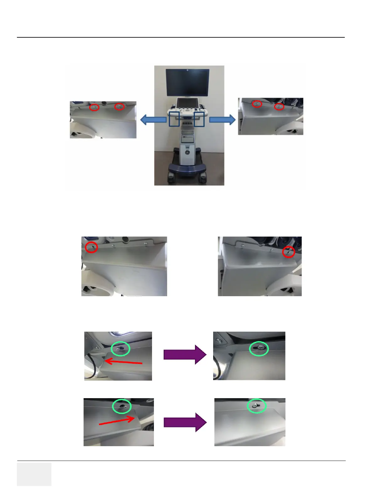
1) Remove 4 screws on AN keyboard Brkt. ( 2 screws on right side and 2 screws on left side)
Figure 8-80 Removal of screws
2) Unscrew 2 screws on AN keyboard Brkt only half . ( 1 screw on right side and 1 screw on left side).
Do not remove these screws.(Red circle in following figure)
Figure 8-81 Half unscrewing points
3) Push the AN keyboard so that screw holes meet the screw head as following figure.
Figure 8-82 Half unscrewing points

Table of Contents

Other manuals for GE LOGIQ P9

Questions and Answers:

Question and Answer IconNeed help?

Do you have a question about the GE LOGIQ P9 and is the answer not in the manual?

GE LOGIQ P9 Specifications

General IconGeneral
TypeUltrasound System
3D/4D ImagingYes
ElastographyYes
ConnectivityDICOM, USB, Ethernet, HDMI
Doppler ModesColor Doppler, Power Doppler
Probesconvex, linear, phased array
Imaging ModesM-Mode, Color Doppler, Power Doppler
PortabilityCart-based
ApplicationsVascular, Cardiac, OB/GYN, Musculoskeletal
WeightApprox. 80 kg
Touch Panel10.1-in touchscreen

Related product manuals