GERAFT LOGIQ P9/P7
D
IRECTION 5604324, REVISION 11 DRAFT (JANUARY 24, 2019) SERVICE MANUAL
8-110 Section 8-17 - Replacement around Nest Box
8-17-11 Handling EEPROM on MCB Board
EEPROM on MCB board contains vital information.
A) System Serial Number that is matched against stored software option key.
B) ComExpress Functional REV that is monitored for sub-system compatibility.
Therefore, when MCB board is replaced, EEPROM must be moved from one board to the other to make
sure vital information pertaining to the system is transferred to the new MCB board.
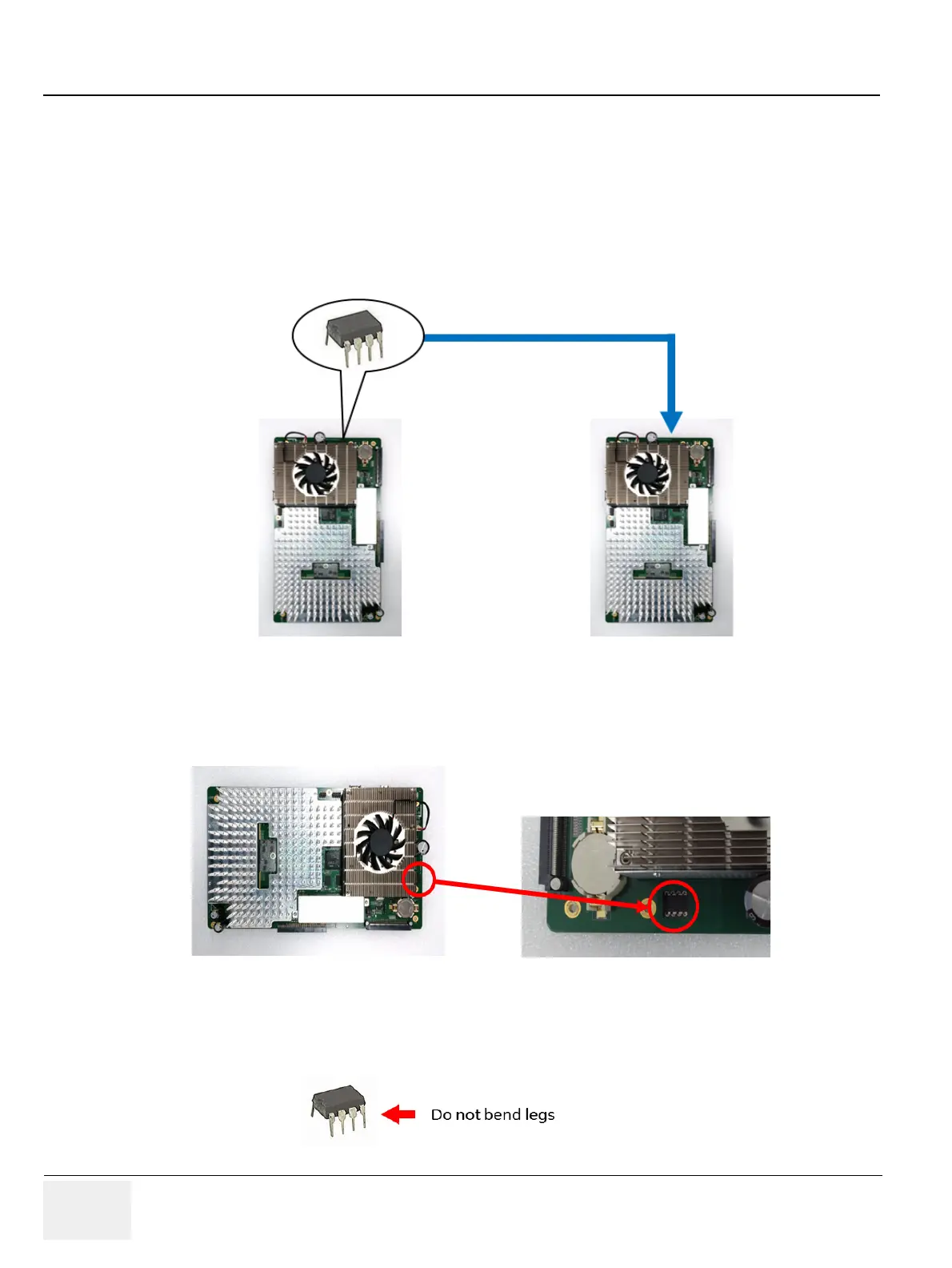
EEPROM must be moved.
Figure 8-122 EEPROM
1) Locate EEPROM on MCB Board.
Figure 8-123 Location of EEPROM (example)
2) Gently lift up EEPROM from its socket by using a chip-puller or a small straight blade screwdriver.
NOTE: Be sure not to bend “legs” of EEPROM. They are fragile.
MCB Board being replaced
New MCB Board

 Loading...


