EasyManuals Logo

GE LOGIQ P9 Service Manual

GE LOGIQ P9
602 pages
To Next Page IconTo Next Page
To Previous Page IconTo Previous Page
Page #485 background imageLoading...
Page #485 background image
GEDRAFT LOGIQ P9/P7
D
IRECTION 5604324, REVISION 11 DRAFT (JANUARY 24, 2019) SERVICE MANUAL
Chapter 8 - Replacement Procedures 8-159
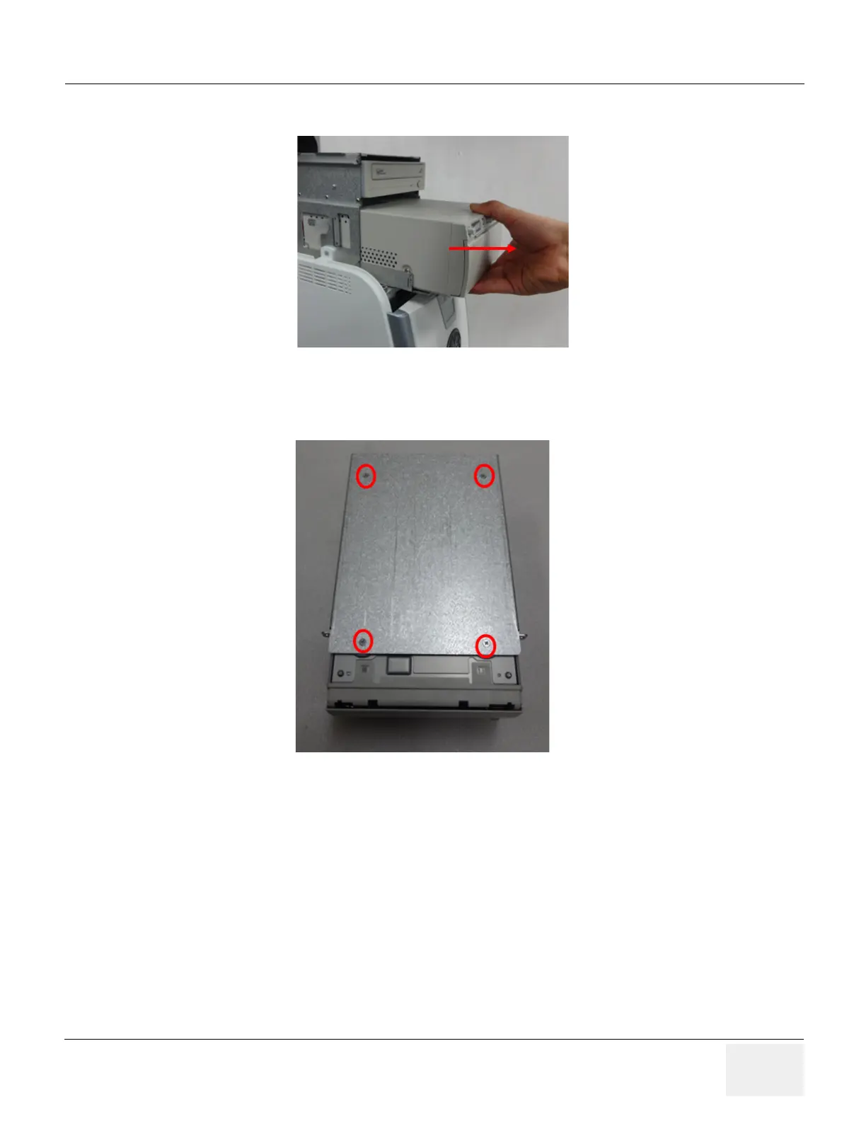
2) Pull out BW printer as following figure.
Figure 8-187 Pulling out the BW printer
3) Remove 4 screws on BW printer bottom part. Refer to following figure.
Figure 8-188 4 screws points
8-35-5 Installation Procedure
1) Parts to be installed in reverse order on removal.
8-35-6 Functional Check
Test 1: Print an image by pressing the button P1 on the operator panel. (P1 key should be configured
correctly. Refer to section 3-8-4 Adding Printer to the system)
Verify1: - Verify that image can be printed.
Verify2: - Verify that printed image has no distortion as compared the image on screen.

Table of Contents

Other manuals for GE LOGIQ P9

Questions and Answers:

Question and Answer IconNeed help?

Do you have a question about the GE LOGIQ P9 and is the answer not in the manual?

GE LOGIQ P9 Specifications

General IconGeneral
TypeUltrasound System
3D/4D ImagingYes
ElastographyYes
ConnectivityDICOM, USB, Ethernet, HDMI
Doppler ModesColor Doppler, Power Doppler
Probesconvex, linear, phased array
Imaging ModesM-Mode, Color Doppler, Power Doppler
PortabilityCart-based
ApplicationsVascular, Cardiac, OB/GYN, Musculoskeletal
WeightApprox. 80 kg
Touch Panel10.1-in touchscreen

Related product manuals