EasyManuals Logo

GE LOGIQ P9 Service Manual

GE LOGIQ P9
602 pages
To Next Page IconTo Next Page
To Previous Page IconTo Previous Page
Page #500 background imageLoading...
Page #500 background image
GERAFT LOGIQ P9/P7
D
IRECTION 5604324, REVISION 11 DRAFT (JANUARY 24, 2019) SERVICE MANUAL
8-174 Section 8-44 - Replacement of MCWD ASSY
Section 8-44
Replacement of MCWD ASSY
8-44-1 Manpower
1 person, 15 minutes
8-44-2 Tools
Standard Phillips Screwdriver.
8-44-3 Removal Procedure
1) Separate MCB Assy and MDC Assy. (Refer to section 8-17-7)
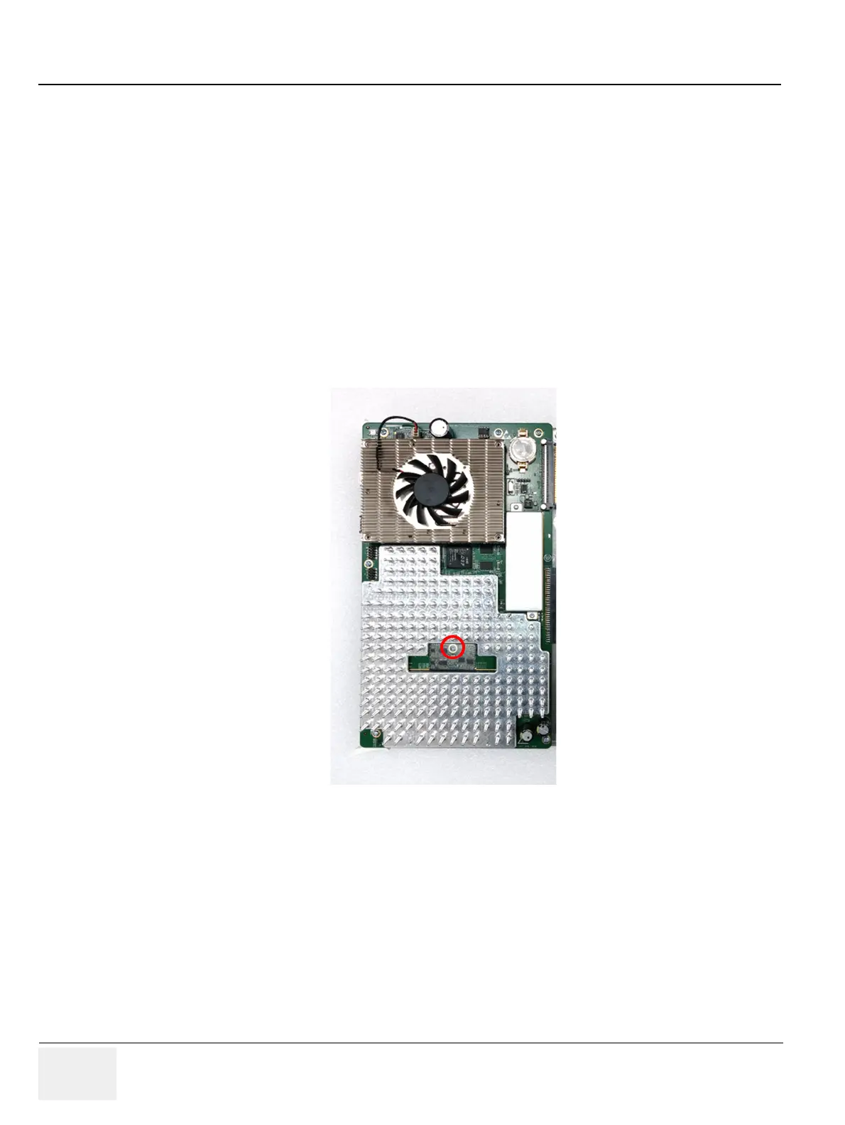
2) Unscrew 1 screw and remove MCWD assy
NOTE: Be careful not to damage MCWD connector.
Figure 8-205 Removal of MCWD board.
8-44-4 Installation Procedure
Parts to be installed in reverse order on removal.
8-44-5 Functional Check
NOTE: Refer to section 4-4 Functional Diag Test List

Table of Contents

Other manuals for GE LOGIQ P9

Questions and Answers:

Question and Answer IconNeed help?

Do you have a question about the GE LOGIQ P9 and is the answer not in the manual?

GE LOGIQ P9 Specifications

General IconGeneral
TypeUltrasound System
3D/4D ImagingYes
ElastographyYes
ConnectivityDICOM, USB, Ethernet, HDMI
Doppler ModesColor Doppler, Power Doppler
Probesconvex, linear, phased array
Imaging ModesM-Mode, Color Doppler, Power Doppler
PortabilityCart-based
ApplicationsVascular, Cardiac, OB/GYN, Musculoskeletal
WeightApprox. 80 kg
Touch Panel10.1-in touchscreen

Related product manuals