EasyManuals Logo

GE LOGIQ P9 Service Manual

GE LOGIQ P9
602 pages
To Next Page IconTo Next Page
To Previous Page IconTo Previous Page
Page #466 background imageLoading...
Page #466 background image
GERAFT LOGIQ P9/P7
D
IRECTION 5604324, REVISION 11 DRAFT (JANUARY 24, 2019) SERVICE MANUAL
8-140 Section 8-26 - Replacement of 4D
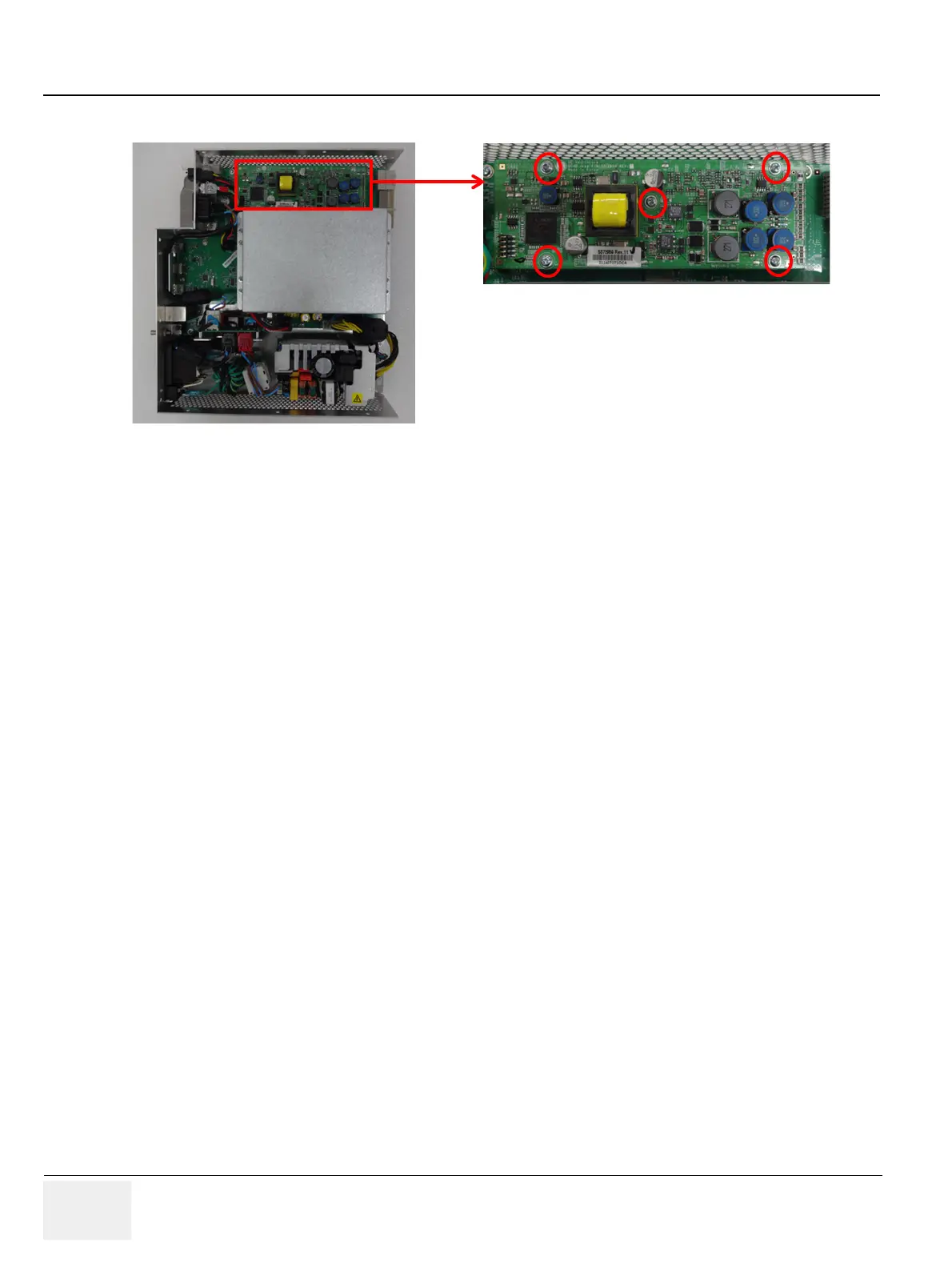
2) Unscrew five screws to remove the DC4D from the IO BOX. Refer to following figure.
Figure 8-164 Screw points of DC4D Assy
3) Carefully lift up the DC4D unit.
8-26-4 Installation Procedure
Install components in reverse order of removal.
8-26-5 Functional Check
Refer to section 4-4 for Functional Diag Test List.

Table of Contents

Other manuals for GE LOGIQ P9

Questions and Answers:

Question and Answer IconNeed help?

Do you have a question about the GE LOGIQ P9 and is the answer not in the manual?

GE LOGIQ P9 Specifications

General IconGeneral
TypeUltrasound System
3D/4D ImagingYes
ElastographyYes
ConnectivityDICOM, USB, Ethernet, HDMI
Doppler ModesColor Doppler, Power Doppler
Probesconvex, linear, phased array
Imaging ModesM-Mode, Color Doppler, Power Doppler
PortabilityCart-based
ApplicationsVascular, Cardiac, OB/GYN, Musculoskeletal
WeightApprox. 80 kg
Touch Panel10.1-in touchscreen

Related product manuals