EasyManuals Logo

GE LOGIQ P9 Service Manual

GE LOGIQ P9
602 pages
To Next Page IconTo Next Page
To Previous Page IconTo Previous Page
Page #433 background imageLoading...
Page #433 background image
GEDRAFT LOGIQ P9/P7
D
IRECTION 5604324, REVISION 11 DRAFT (JANUARY 24, 2019) SERVICE MANUAL
Chapter 8 - Replacement Procedures 8-107
8-17-8 Removal Procedure - Separating MPI and MCB
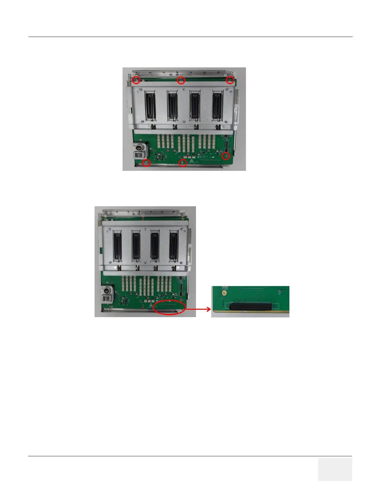
1) Unscrew 6 screws. Refer to following figure.
Figure 8-116 Screw points on MPI assy
2) Carefully separate MPI assy from MCB assy. Refer to following figure.
Figure 8-117 Lifting up MPI and position of Stacking up connector on MPI assy

Table of Contents

Other manuals for GE LOGIQ P9

Questions and Answers:

Question and Answer IconNeed help?

Do you have a question about the GE LOGIQ P9 and is the answer not in the manual?

GE LOGIQ P9 Specifications

General IconGeneral
TypeUltrasound System
3D/4D ImagingYes
ElastographyYes
ConnectivityDICOM, USB, Ethernet, HDMI
Doppler ModesColor Doppler, Power Doppler
Probesconvex, linear, phased array
Imaging ModesM-Mode, Color Doppler, Power Doppler
PortabilityCart-based
ApplicationsVascular, Cardiac, OB/GYN, Musculoskeletal
WeightApprox. 80 kg
Touch Panel10.1-in touchscreen

Related product manuals