EasyManuals Logo

GE LOGIQ P9 Service Manual

GE LOGIQ P9
602 pages
To Next Page IconTo Next Page
To Previous Page IconTo Previous Page
Page #434 background imageLoading...
Page #434 background image
GERAFT LOGIQ P9/P7
D
IRECTION 5604324, REVISION 11 DRAFT (JANUARY 24, 2019) SERVICE MANUAL
8-108 Section 8-17 - Replacement around Nest Box
8-17-9 Removal Procedure - Separating DCWD Board(Option) from MPI
Philips screw-driver required to add this part.
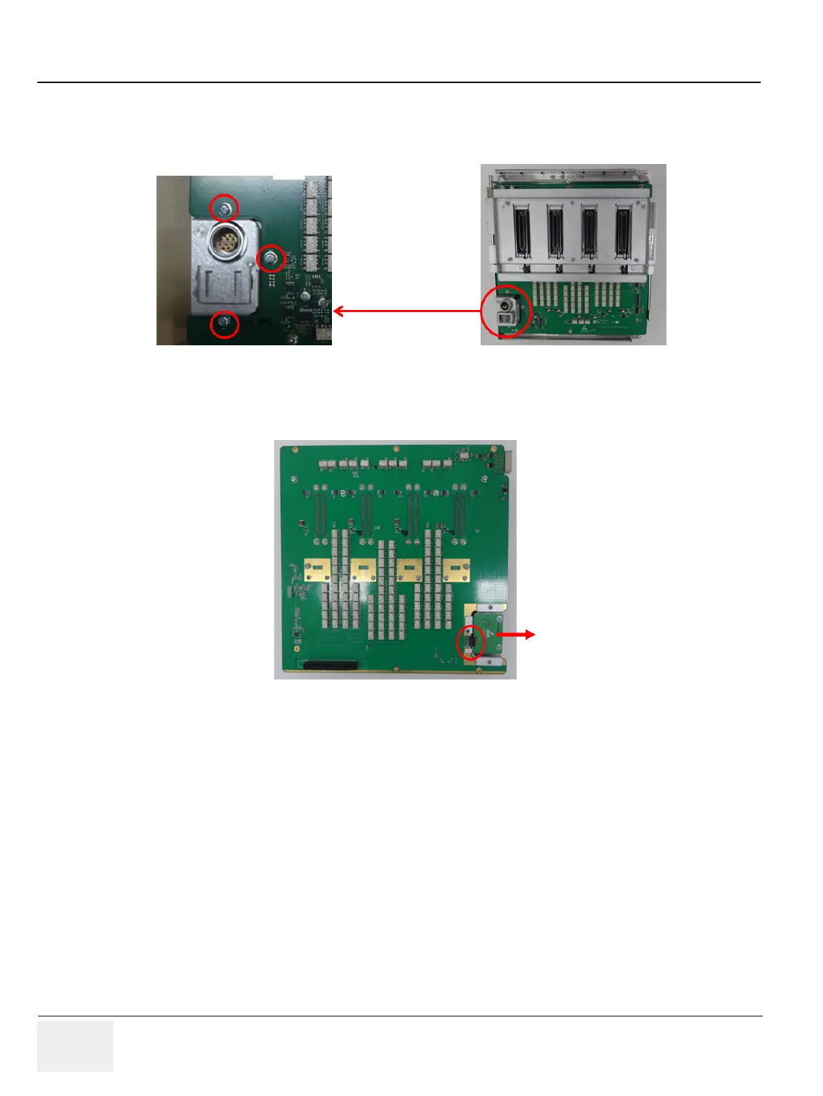
1) Remove 3 screws on MPI assy.
Figure 8-118 DCWD Board screw points
2) Carefully separate DCWD board from MPI assy not to damage the DCWD connector. Refer to
following figure.
Figure 8-119 Position of DCWD board connector

Table of Contents

Other manuals for GE LOGIQ P9

Questions and Answers:

Question and Answer IconNeed help?

Do you have a question about the GE LOGIQ P9 and is the answer not in the manual?

GE LOGIQ P9 Specifications

General IconGeneral
TypeUltrasound System
3D/4D ImagingYes
ElastographyYes
ConnectivityDICOM, USB, Ethernet, HDMI
Doppler ModesColor Doppler, Power Doppler
Probesconvex, linear, phased array
Imaging ModesM-Mode, Color Doppler, Power Doppler
PortabilityCart-based
ApplicationsVascular, Cardiac, OB/GYN, Musculoskeletal
WeightApprox. 80 kg
Touch Panel10.1-in touchscreen

Related product manuals