EasyManuals Logo

GE LOGIQ P9 Service Manual

GE LOGIQ P9
602 pages
To Next Page IconTo Next Page
To Previous Page IconTo Previous Page
Page #475 background imageLoading...
Page #475 background image
GEDRAFT LOGIQ P9/P7
D
IRECTION 5604324, REVISION 11 DRAFT (JANUARY 24, 2019) SERVICE MANUAL
Chapter 8 - Replacement Procedures 8-149
8-29-2 B/W Printer Cables
8-29-2-1 Manpower
1 person, 5 minutes.
8-29-2-2 Tools
Standard Phillips Screwdriver.
8-29-2-3 Pre work
1) Remove Rear Cover. (refer to section 8-9)
2) Remove Top Cover (refer to section 8-7)
3) Remove Cable Cover Bracket. (refer to section 8-17)
8-29-2-4 Removal Procedure
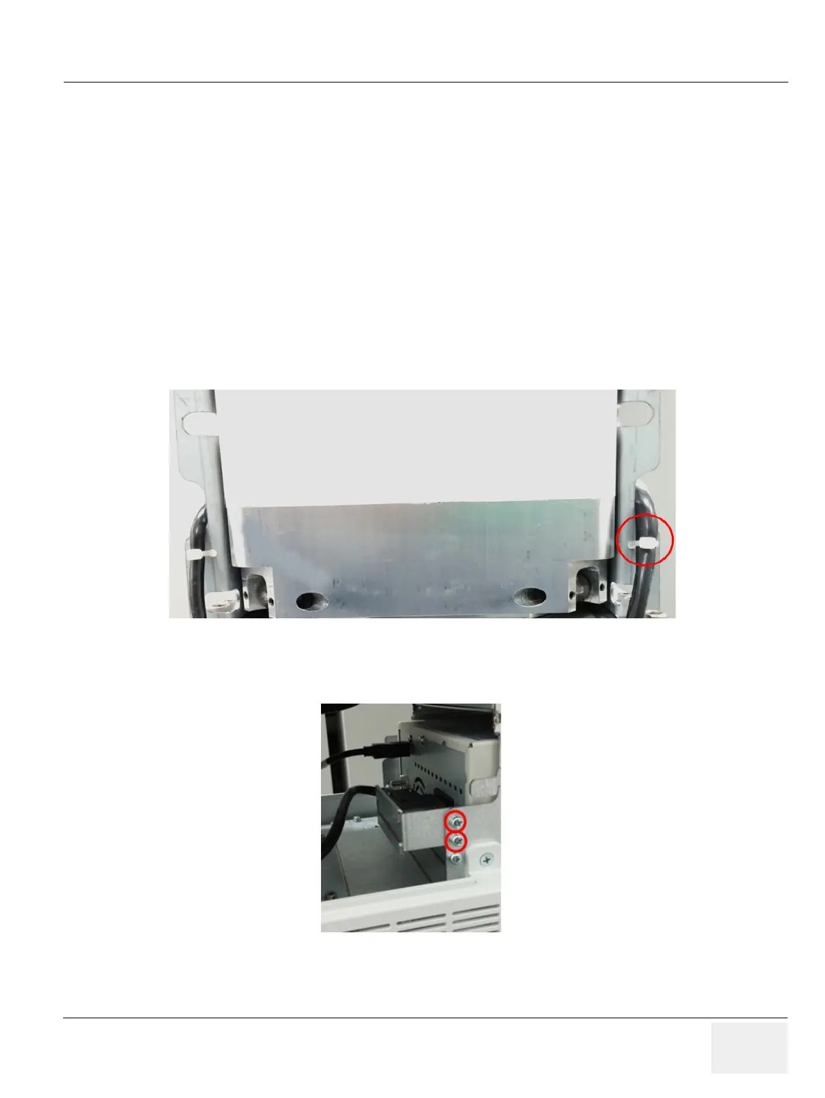
1) Remove the cable tie.
Figure 8-174 Cable tie point
2) Remove 2 screws on left side of BW printer and remove BW printer Power fix Bracket
Figure 8-175 Screw points to remove BW power fix bracket.

Table of Contents

Other manuals for GE LOGIQ P9

Questions and Answers:

Question and Answer IconNeed help?

Do you have a question about the GE LOGIQ P9 and is the answer not in the manual?

GE LOGIQ P9 Specifications

General IconGeneral
TypeUltrasound System
3D/4D ImagingYes
ElastographyYes
ConnectivityDICOM, USB, Ethernet, HDMI
Doppler ModesColor Doppler, Power Doppler
Probesconvex, linear, phased array
Imaging ModesM-Mode, Color Doppler, Power Doppler
PortabilityCart-based
ApplicationsVascular, Cardiac, OB/GYN, Musculoskeletal
WeightApprox. 80 kg
Touch Panel10.1-in touchscreen

Related product manuals