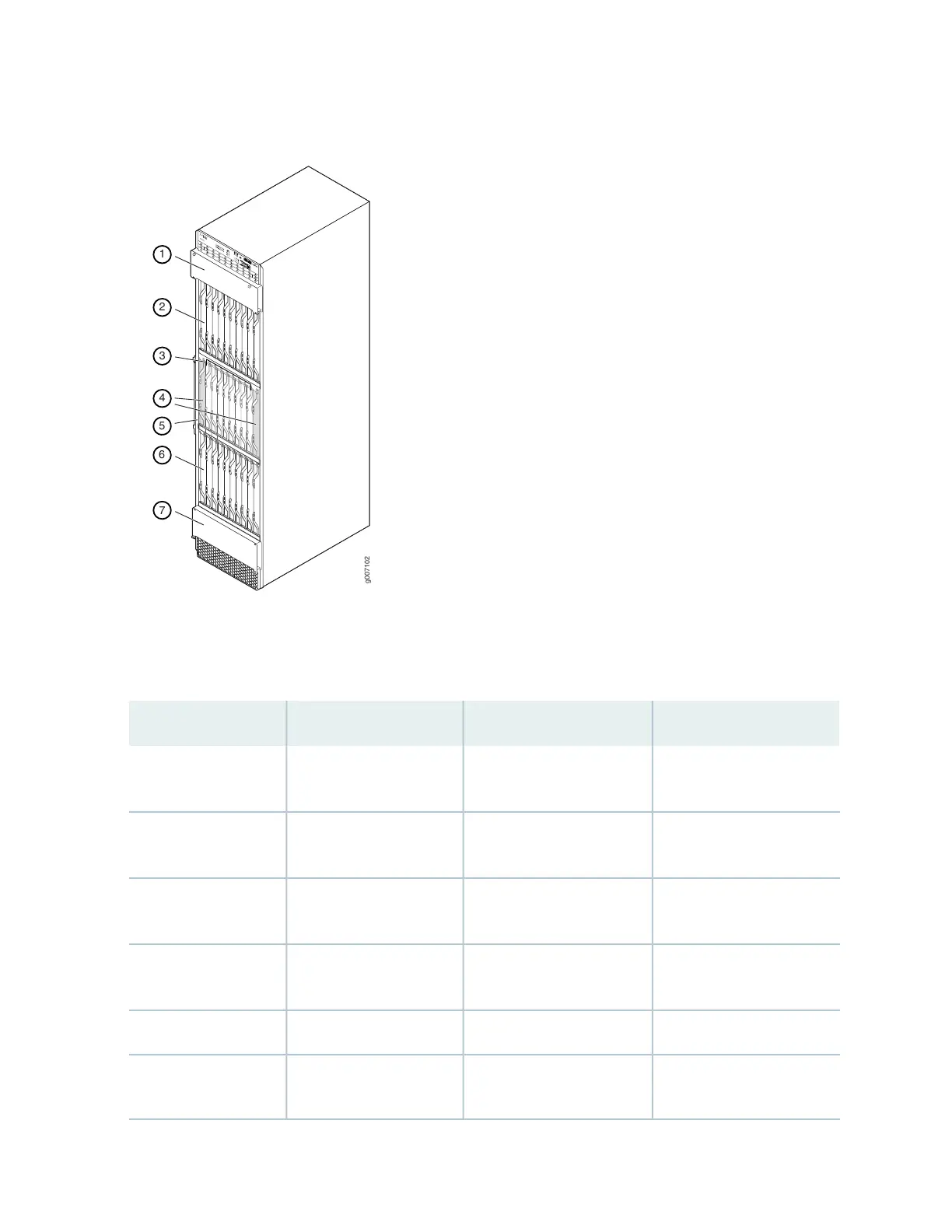
Figure 1: Front View of a Fully Configured MX2020 Router Chassis
g007102
RE0
RE1
MASTER
ONLINE
OFFLINE
PSM
1
2
3
4
5
6
7
8
0
10
11
12
13
14
15
16
17
9
MX2200
LC
CB-RE
LC
SFB
10
0
0
11
0
1
12
1
2
13
2
3
14
3
4
15
4
5
16
5
6
17
6
7
18
7
8
19
1
9
LC
CB-RE
LC
SFB
2
1
6
7
4
3
5
Remove field replacement units (FRUs) from the front of the MX2020 router before you install the router.
See Table 3 on page 7 for information on MX2020 router components.
Table 3: Front Components in a Fully Configured MX2020 Router
Number of FRUsSlotsComponent DescriptionComponent No.
1–Upper cable manager–
(standard or extended)
1
1010 through 19 (top)MPCs with ADCs and
MICs (top)
2
80 through 7Switch Fabric Boards
(SFBs)
3
20 and 1Control Board and Routing
Engine (CB-RE)
4
1–Middle card cage air filter5
100 through 9MPCs with ADCs and
MICs (bottom)
6
7