Establishing the electrical connection
Pin Assignment
1 Spare
2 Spare
3 PROFIBUS connection B
4 TTL signal RTS
5 Ground
6 +5 V for bus terminal
7 Spare
8 PROFIBUS connection A
9 Spare
Tab. 69 Pin assignment of SUB-D 9-pole interface on the PROFIBUS module
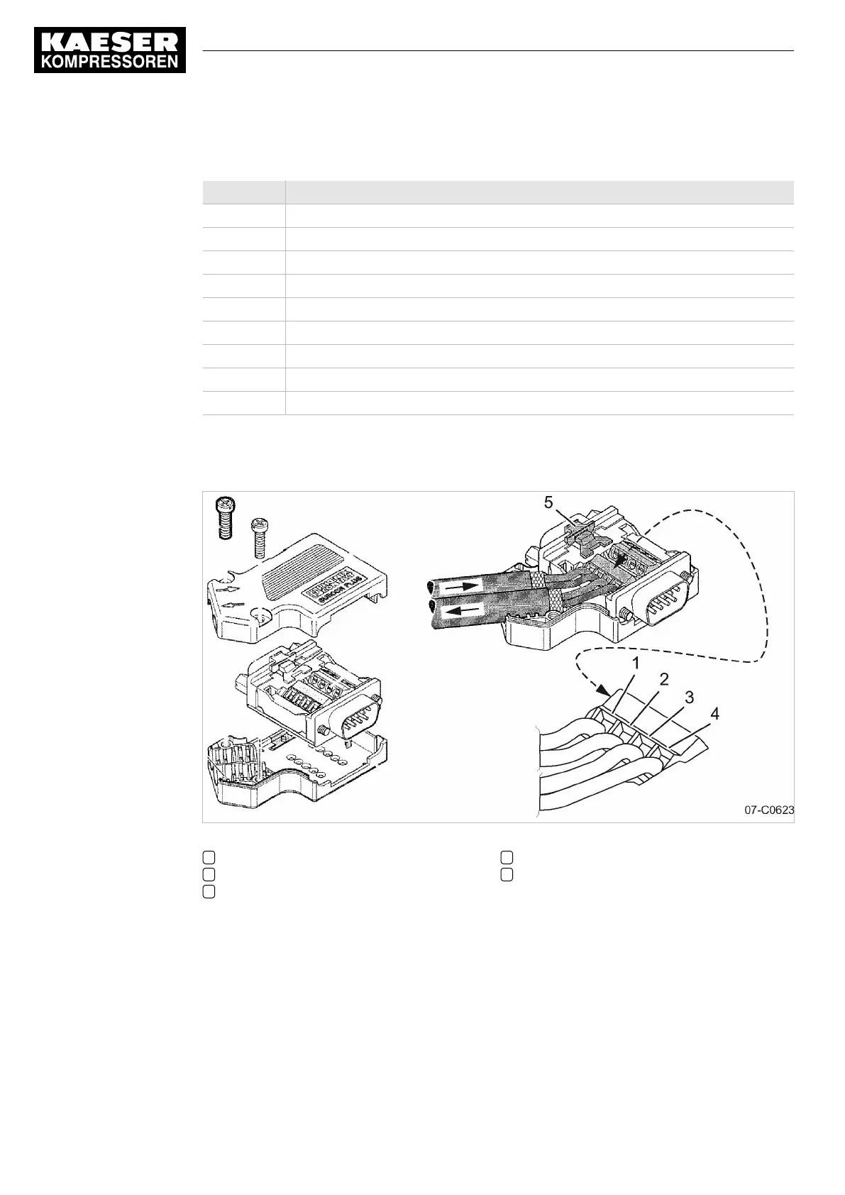
Interface plug wiring
Fig. 30 PROFIBUS plug wiring
1 Terminal 1A
2 Terminal 1B
3 Terminal 2A
4 Terminal 2B
5 Slide switch, terminating resistor
8 Initial Start-up
8.10 Configuring the machine for master control
124
User Manual Controller
SIGMA CONTROL 2 SCREW FLUID ≥5.1.2 No.: 9_9450 13 USE