2. Press «Enter».
The display for the message type flashes.
3. Use «Up» or «Down» to set the message type.
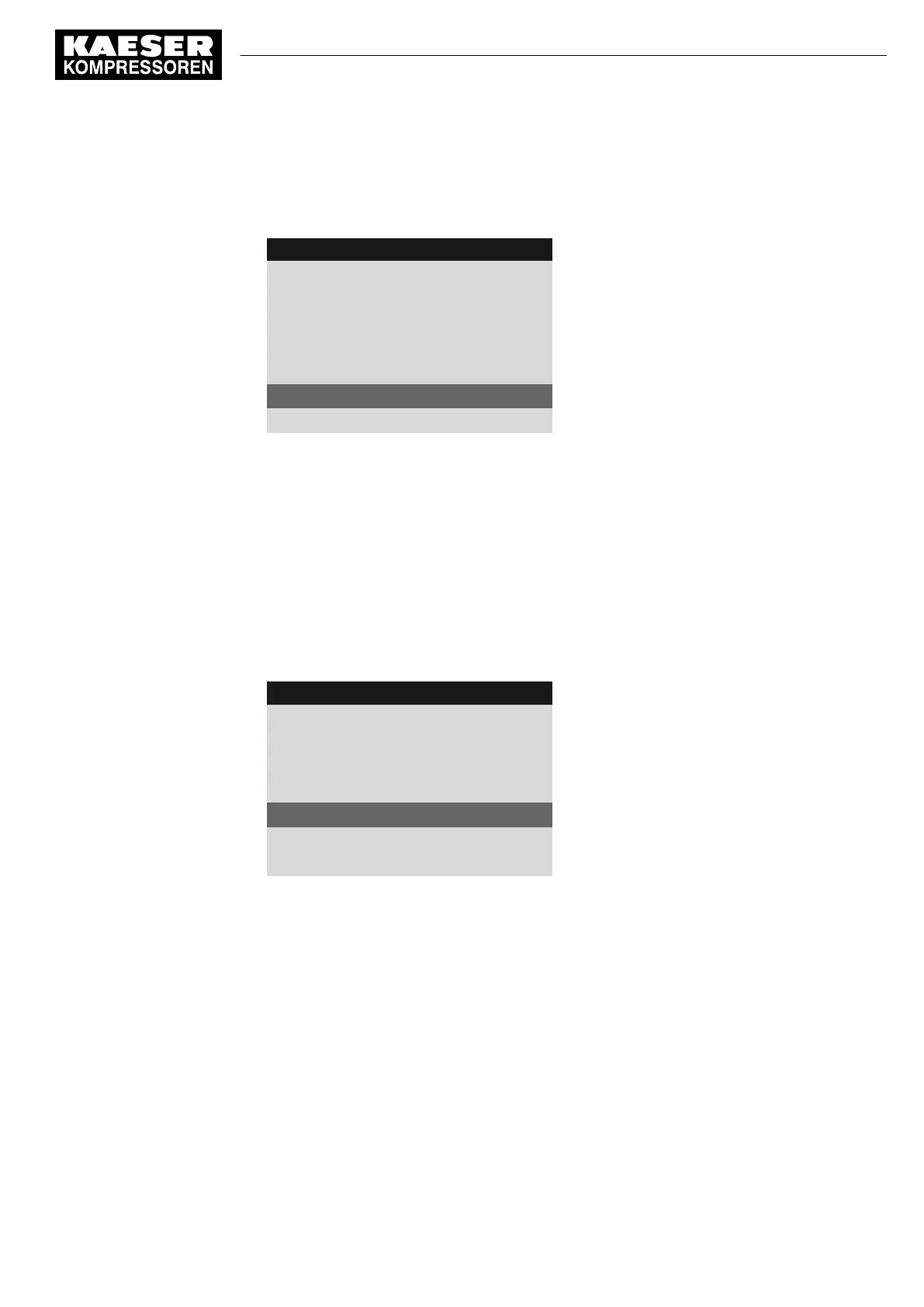
8 8 p s i 0 8 : 1 5 A M 1 7 6 ° F
Header
5.7.3.1 External message 1
Menu
External message 1
Message text
DI1.07 ok ☑
Input selected
td: 0s ¦ Logic : +
Active line, set logic control field
DOR1.04 ☐
Warning ☑
Example: Warning message type
4. Press «Enter».
The message type is set.
8.11.2.7 Assigning and activating the output
1. Use «Up» or «Down» to select the
DOR
line.
2. Press «Enter».
The
DOR
output display flashes.
3. Select the output with the «Up» and «Down» keys.
4. Press «Enter».
The setting is applied.
8 8 p s i 0 8 : 1 5 A M 1 7 6 ° F
Header
5.7.3.1 External message 1
Menu
External message 1
Message text
DI1.07 ok ☑
Input selected
td: 0s ¦ Logic : +
Active line, set logic control field
DOR1.01 ☑
Output is selected and activated
Warning ☑
Example: Warning message type
5. Press the «Right» arrow.
6. Press «Enter».
The check box assigned to the output flashes.
7. Press the «Up» key.
The check box is activated.
8. Press «Enter».
The output is assigned and activated.
Result The signal at the DI digital input is available as
External message 1
and as output signal at the
selected DOR output.
8.11.3 Output measured values on the display
For analog measured values you can define customized messages.
8 Initial Start-up
8.11 Setting input and output signals
No.: 9_9450 13 USE
User Manual Controller
SIGMA CONTROL 2 SCREW FLUID ≥5.1.2
157