Establishing the electrical connection
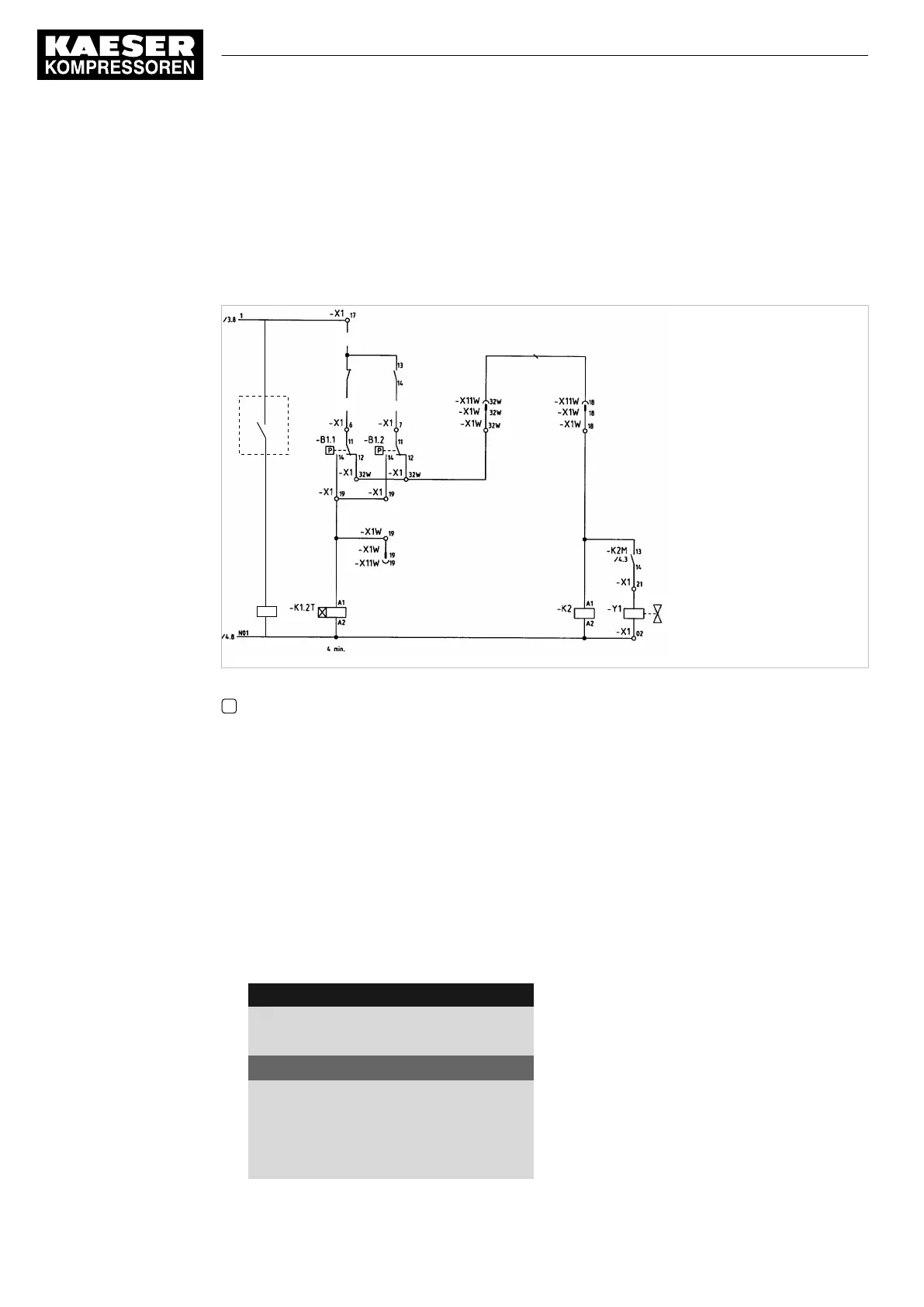
■ Contact A open: SIGMA CONTROL 2 controls with system setpoint pressure pB
■ Contact A closed: SIGMA CONTROL 2 controls with system setpoint pressure pA
■ B 1.1: Pressure switch for system setpoint pressure pB
■ B 1.2: Pressure switch for system setpoint pressure pA
07-S0629
A
-K3
A1
A2
Fig. 38 Machine with pressure switch regulation
A Floating relay contact SIGMA CONTROL 2
➤ Make the electrical connection according to the diagram.
Set the system setpoint pressure pA and pB.
Precondition Password access level 2 is activated.
The electrical connection is made.
1. Open the
<5.2.2 – Pressure control – Pressure settings>
menu (see chapter 8.4.1).
2. Use «Up» or «Down» to select the
pASP
line.
3. Press «Enter».
The setting mode is active.
The
Setpoint pressure pA
display flashes.
8 8 p s i 0 8 : 1 5 A M 1 7 6 ° F
Header
5.2.2 Pressure settings
Menu
Setpoint pressure
pA SP: 123psi ¦ SD: −7.3psi
Active line
pB SP: 119psi ¦ SD: −7.3psi
·········
System pressure low ☐
↓ < 72.5psi ¦ SD: 7.2psi
8 Initial Start-up
8.10 Configuring the machine for master control
146
User Manual Controller
SIGMA CONTROL 2 SCREW FLUID ≥5.1.2 No.: 9_9450 13 USE