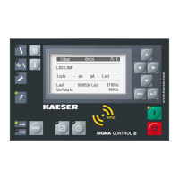
4. Press the «Enter» key.
The threshold is selected and activated.
Result In the above example the switching point for
System pressure pNloc
has been set and is active. If
the pressure is reached or exceeded and remains longer than the set time delay
td
, the message is
triggered with the set message type and the set output
DOR
is switched. If the pressure falls below
the threshold
SP
+ switching differential
SD
, the message and output are reset. The switching be‐
havior is inverted by setting "-" of
Logic
parameter.
The settings for the other measured values are carried out in the same manner.
8.12 Timer
SIGMA CONTROL 2 is equipped with an integrated timer that can control an adjustable DOR out‐
put for customer-specific applications. Valid setting values for the cutting in and out duration are
between 10 h ≥ t ≥ 1 s.
Precondition Access level 2 is activated
The electrical connection has been established (for information about a spare
DOR
output please
see the machine's wiring diagram)
1. Open the 5.8
<Configuration – Timer>
menu.
8 8 p s i 0 8 : 1 5 A M 1 7 6 ° F
Header
5.8 Timer
Menu
on :
00h:00m:00s
Cut-in period
off :
00h:00m:00s
Cut-out period
DOR1.02 ☐
set output
·········
current off
Current status DOR
00h:00m:00s
Remaining time until status change
2. Using the «Up» or «Down» key, select the line
on
.
3. Press the «Enter» key.
Setting mode is active.
The display for hours
00h:00m:00s
flashes.
4. Use «Up» or «Down» to set the hours.
5. Press the «Right» key.
The display for minutes
01h:00m:00s
flashes.
6. Use «Up» or «Down» to set the minutes.
7. Press the «Right» key.
The display for seconds
01h:15m:00s
flashes.
8. Use «Up» or «Down» to set the seconds.
9. Press the «Enter» key.
The setting is applied accordingly.
10. Use the «Up» or «Down» keys to select the
off
line.
11. Proceed in the same manner to set the cut-out period.
12. Use the «Up» or «Down» keys to select the
DOR
line.
8 Initial Start-up
8.12 Timer
No.: 9_9450 13 USE
User Manual Controller
SIGMA CONTROL 2 SCREW FLUID ≥5.1.2
167

 Loading...