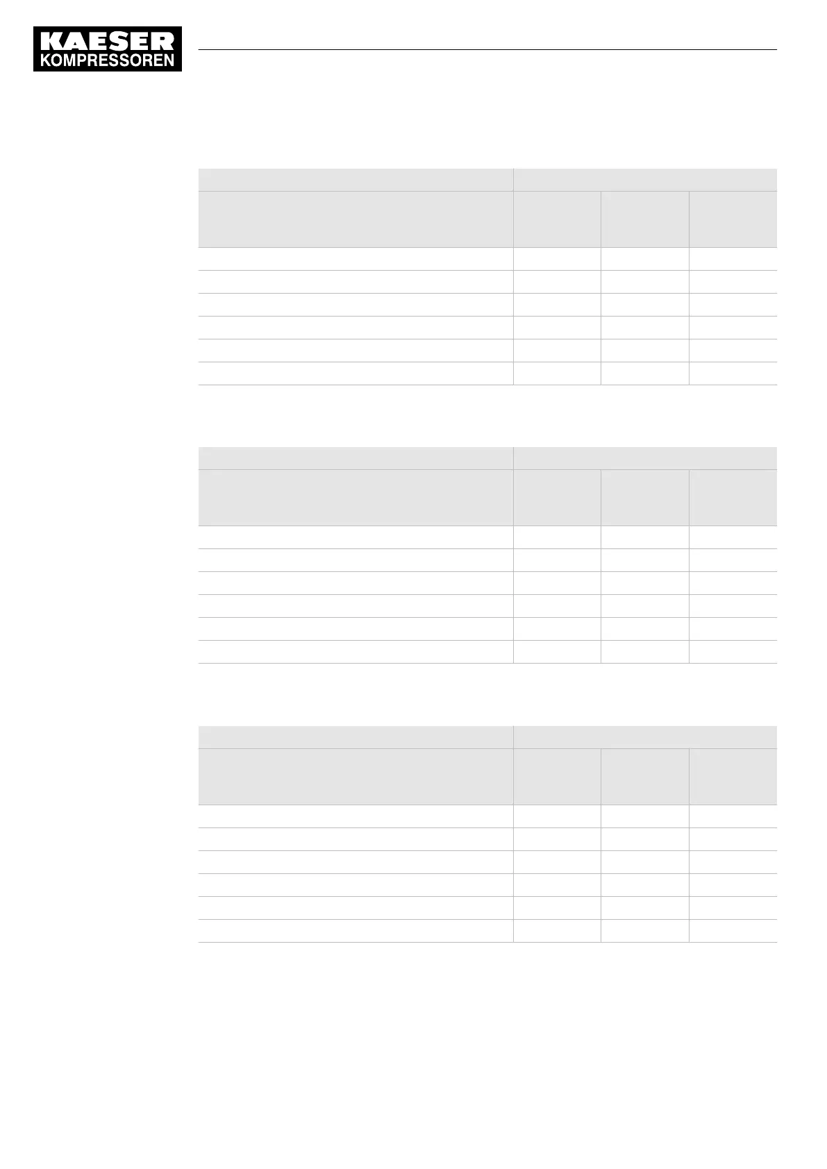
IOM 1
Input/Output Input/output module 1
Internal, into
the control
cabinet
Available in
parallel on
both sides
External, into
the compres‐
sor interior
Digital input (DI), 24 VDC 4 10 2
Analog input current (AII), 0–20 mA – 1 2
Analog input resistor (AIR), Pt100 – 1 3
Digital output relay (DOR), 250 VAC, 8 A 8 – –
Digital output transistor (DOT), 24 VDC, 0.5 A – 2 1
Analog output current (AOI), 0–20 mA – – –
Tab. 16 IOM-1
IOM 2
Input/Output Input/output module 2
Internal, into
the control
cabinet
Available in
parallel on
both sides
External, into
the compres‐
sor interior
Digital input (DI), 24 VDC 6 – 2
Analog input current (AII), 0–20 mA – 1 2
Analog input resistor (AIR), Pt100 – 3 –
Digital output relay (DOR), 250 VAC, 8 A 4 – –
Digital output transistor (DOT), 24 VDC, 0.5 A – 2 2
Analog output current (AOI), 0–20 mA – 1 –
Tab. 17 IOM-2
IOM 3
Input/Output Input/output module 3
Internal, into
the control
cabinet
Available in
parallel on
both sides
External, into
the compres‐
sor interior
Digital input (DI), 24 VDC 6 – 2
Analog input current (AII), 0–20 mA – 1 3
Analog input resistor (AIR), Pt100 – 3 8
Digital output relay (DOR), 250 VAC, 8 A 8 – –
Digital output transistor (DOT), 24 VDC, 0.5 A – 1 1
Analog output current (AOI), 0–20 mA – 1 –
Tab. 18 IOM-3
3 Technical Data
3.1 Controller SIGMA CONTROL 2
14
User Manual Controller
SIGMA CONTROL 2 SCREW FLUID ≥5.1.2 No.: 9_9450 13 USE