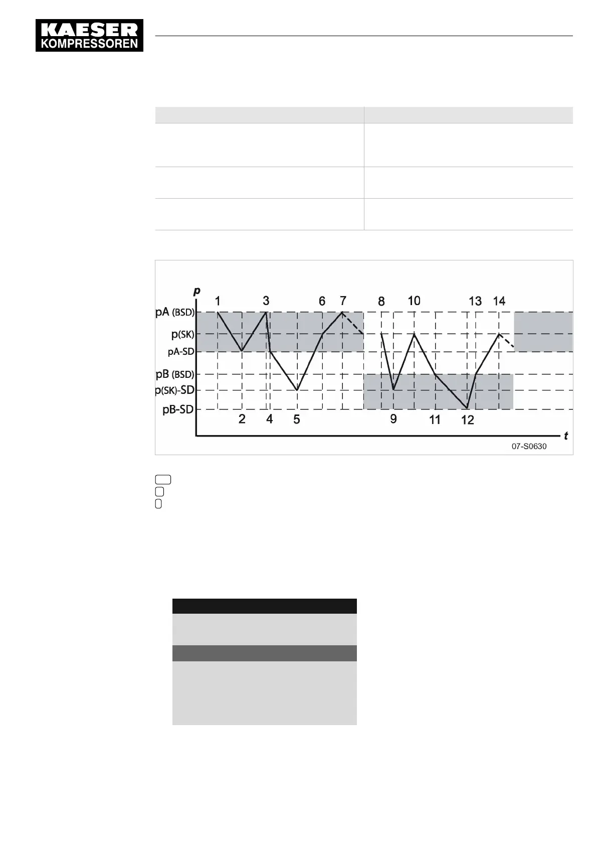
Period t1–t7: high air demand Period t8–t14: low air demand
t5:
SK also switches to LOAD.
System pressure pNloc begins to rise.
t12:
SK switches to LOAD.
System pressure pNloc begins to rise.
t6:
SK switches to IDLE.
t13:
SK switches to IDLE.
t7:
BSD switches to IDLE.
t14:
BSD switches to IDLE.
Tab. 71 Function diagram
Fig. 39 Function diagram
SD Switching differential
p Pressure
t Time
Set the system setpoint pressure pA and pB.
Precondition Password access level 2 is activated.
1. Open the
<5.2.2 – Pressure control – Pressure settings>
menu (see chapter 8.4.1).
2. Use «Up» or «Down» to select the
pASP
line.
8 8 p s i 0 8 : 1 5 A M 1 7 6 ° F
Header
5.2.2 Pressure settings
Menu
Setpoint pressure
pA SP: 123psi ¦ SD: −7.3psi
Active line
pB SP: 119psi ¦ SD: −7.3psi
·········
System pressure low ☐
↓ < 72.5psi ¦ SD: 7.2psi
3. Press «Enter».
The
pA
display flashes.
8 Initial Start-up
8.10 Configuring the machine for master control
No.: 9_9450 13 USE
User Manual Controller
SIGMA CONTROL 2 SCREW FLUID ≥5.1.2
149