8.10.2.1 Reaction in the event of a communication malfunction
After switching on the power supply, monitoring for communication malfunctions is suppressed for
a period of time which can be defined by means of the
Start td
parameter. The setting depends on
the time passing at the bus master between return of power and start of communication via the
bus.
For the communication with SAM 4.0, the value of Start td must be set to 30 s.
SIGMA CONTROL 2 can monitor the bus communication at user level. For this purpose, the bus
master reads a value ("toggle bit") that changes with every bus cycle and returns it without change.
SIGMA CONTROL 2 returns a communication malfunction if the value does not change for a time
longer than set (
Timeout
).
Monitoring for communication malfunction can be activated if needed. For this purpose, the
Send/receive
option must be set for the data exchange. Activate the
Communication error
check box to enable monitoring for communication malfunctions.
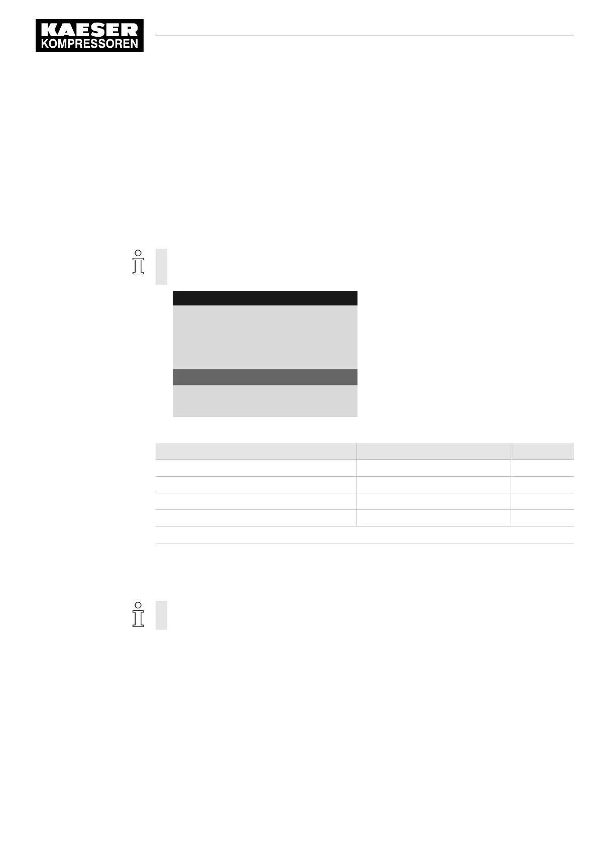
8 8 p s i 0 8 : 1 5 A M 1 7 6 ° F
Header
8.1.2.2 SAM 4.0
Menu
IP address : 169.254.100.100
Port : 2000
·········
Communication error : ☑
Active line
Start td 30s
Timeout : 5s ☑
Settings for connection to SAM 4.0.
Parameters Factory setting Set value
Check box Communication error
Check box ☑ activated
1)
Start td 30 s
Timeout 5 s
Check box Timeout Check box ☑ activated
1)
Prerequisite: The
Send/receive
option has been set.
Tab. 68 Parameters for monitoring for communication malfunction
8.10.3 Configuring PROFIBUS mode (SIGMA AIR MANAGER)
Only possible with SIGMA CONTROL 2 (prepared for connection to control center)
Overview:
■ PROFIBUS DP-V0 Retrofit Kit required
■ Establishing the electrical connection
■ Setting the remote operating mode
pB
.
■ Setting the PROFIBUS interface
■ Activating the «Remote control» key
Precondition Retrofit kit PROFIBUS required
8 Initial Start-up
8.10 Configuring the machine for master control
No.: 9_9450 13 USE
User Manual Controller
SIGMA CONTROL 2 SCREW FLUID ≥5.1.2
123