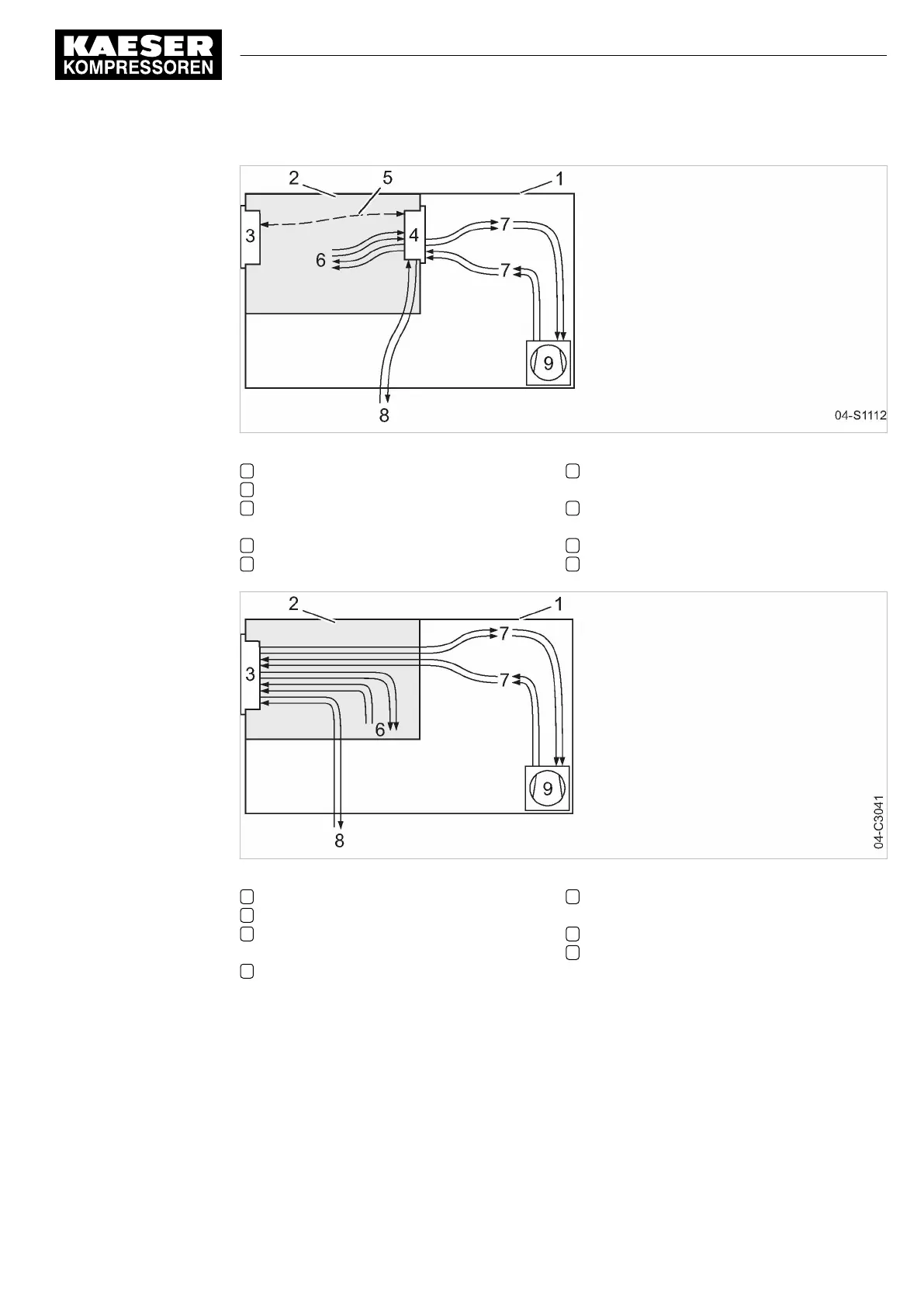
Fig. 5 MCS system design with IOM
1 Machine enclosure
2 Control cabinet
3 SIGMA CONTROL 2 (Prepared for con‐
nection to control center)
4 Input-Output-Module (IOM):
5 I/O bus
6 Inputs/outputs in the interior of the control
cabinet
7 Inputs/outputs in the interior of the com‐
pressor
8 Inputs/outputs for external sensors
9 Compressor
Fig. 6 MCSIO system design
1 Machine enclosure
2 Control cabinet
3 SIGMA CONTROL 2 (Connection to con‐
trol technology not provided)
6 Inputs/outputs in the interior of the control
cabinet
7 Inputs/outputs in the interior of the com‐
pressor
8 Inputs/outputs for external sensors
9 Compressor
Function
The control and regulating function allows:
■ Automatic changeover of the machine from LOAD to IDLE (not for AIRTOWER) or READY.
■ Optimum utilization of the motor adjusted to the actual compressed air demand.
■ Automatic restart of the machine after a power failure (can be deactivated).
5 Design and Function
5.1 Controller overview
No.: 9_9450 13 USE
User Manual Controller
SIGMA CONTROL 2 SCREW FLUID ≥5.1.2
19