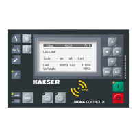
4. Use «Up» or «Down» to set the value for
pA
.
5. Press «Enter».
The setting is applied.
6. If necessary, adjust the value for
SD
in the same manner.
7. If necessary, adjust the value for
pB/SD
in the same manner.
8. Press «Escape» repeatedly to leave this menu.
Setting local mode
➤ Set the clock program or clock as described in section 8.9.
Assigning the potential-free contact (activate)
Precondition Password access level 2 is activated.
The electrical connection made (select spare contact from the machine's electrical diagram).
1. Select the 5.2.3
<Configuration – Pressure control – Load control>
menu.
2. Using the «Up» or «Down» key, select the line
pA/pB DO
.
8 8 p s i 0 8 : 1 5 A M 1 7 6 ° F
Header
5.2.3 Load control
Menu
pA/pB RC DI1.10 ☐
Logic : +
pA/pB DO DOR1.03 ☐
Active line, no output assigned
Logic : +
·········
Load RC DI1.03 ok ☑
3. Press «Enter».
The setting mode is active.
4. Use «Up» or «Down» to set the required output.
5. Press «Enter».
The setting is applied.
Result This output can now be used for the changeover between the two pressure switches.
Setting local mode
Precondition Password access level 2 is activated.
1. Open the 5.2.3
<Configuration – Pressure control – Load control>
menu.
8 Initial Start-up
8.10 Configuring the machine for master control
No.: 9_9450 13 USE
User Manual Controller
SIGMA CONTROL 2 SCREW FLUID ≥5.1.2
147

 Loading...