2N8/2N7
1-2-70
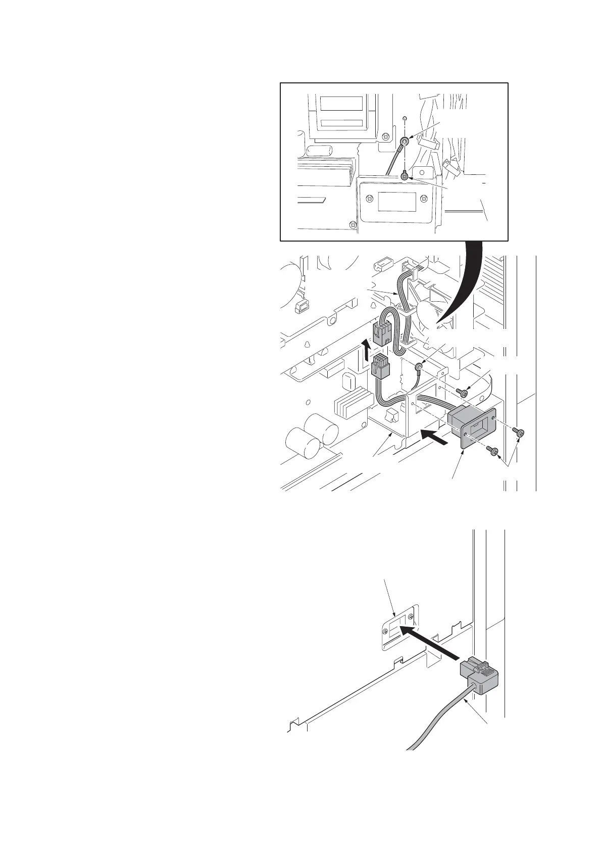
13. Pass the vender wire through the aper-
ture in the IF mount.
14. Secure the vender wire with two screws
removed in step 10.
15. Secure the ground terminal of the
vender wire to rear frame with the
screw.
16. Connect the connector of the vender
wire to connector of the vender signal
cable.
Figure 1-2-105
17. Refit the rear lower cover, toner dis-
posal box and rear upper cover.
18. Connect the signal cable of coin vender
to connector of the vender wire.
Figure 1-2-106
Screws
Vender wire
Ground terminal
Screw
Ground
terminal
Screw
Vender
signal cable
IF mount
Signal cable
of coin vende
Vender wire







 To Next Page