Gocator Line Profile Sensors: User Manual
Gocator Web Interface • 152
after it has been generated, but the
generation itself does not depend
on the detection logic. To do this,
check Enabled in the Part
Detection panel.
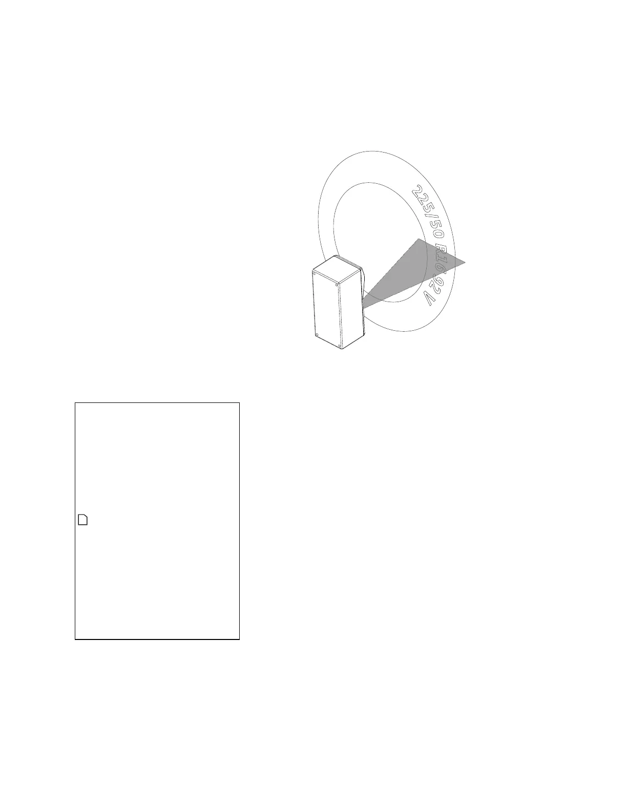
Rotational: The sensor reorders
profiles within a surface to be
aligned with the encoder’s index
pulse. That is, regardless of the
radial position the sensor is started
at, the generated surface always
starts at the position of the index
pulse. If the index pulse is not
detected and the rotation
circumference is met, the surface is
dropped and the Encoder Index
Drop indicator will be
incremented.This mode is typically
used in applications where
measurements of circular objects or
shafts need to be taken, such as tire
tread inspection, or label
positioning on bottles.
To scan exactly one
revolution of a circular
target without knowing
the circumference,
manually set the encoder
resolution (page106) to
1, the encoder trigger
spacing (page 117) to
(number of encoder ticks
per revolution) / (number
of desired profiles per
revolution), and Encoder
Resolution in the
Surface Generation
panel to the number of
encoder ticks per
revolution.
You can optionally enable part
detection to process the surface
after it has been generated, but the
generation itself does not depend
 Loading...