Gocator Line Profile Sensors: User Manual
Specifications • 766
Sensor Connectors
The following sections provide the specifications of the connectors on Gocator sensors.
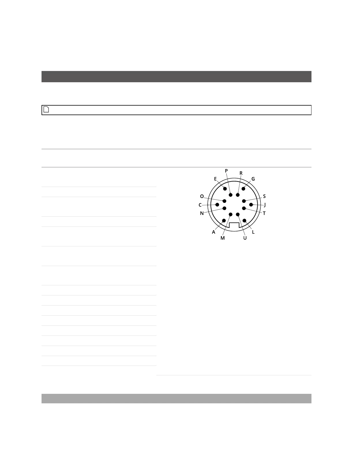
Gocator Power/LAN Connector
The Gocator Power/LAN connector is a 14 pin, M16 style connector that provides power input, laser
safety input and Ethernet.
This connector is rated IP67 only when a cable is connected or when a protective cap is used.
This section defines the electrical specifications for Gocator Power/LAN Connector pins, organized by
function.
Function Pin
Lead Color on
Cordset
GND_24-48V L White/
Orange & Black
View: Looking into the connector on the sensor
GND_24-48V L Orange/ Black
DC_24-48V A White/
Green & Black
DC_24-48V A Green/ Black
Safety- G White/ Blue &
Black
Safety+ J Blue/
Black
Sync+ E White/
Brown & Black
Sync- C Brown/ Black
Ethernet MX1+ M White/ Orange
Ethernet MX1- N Orange
Ethernet MX2+ O White/ Green
Ethernet MX2- P Green
Ethernet MX3- S White/ Blue
Ethernet MX3+ R Blue
Ethernet MX4+ T White/ Brown
Ethernet MX4- U Brown
Gocator Power/LAN Connector Pins
Two wires are connected to the ground and power pins.
Grounding Shield
The grounding shield should be mounted to the earth ground.
 Loading...

