Gocator Line Profile Sensors: User Manual
How Gocator Works • 59
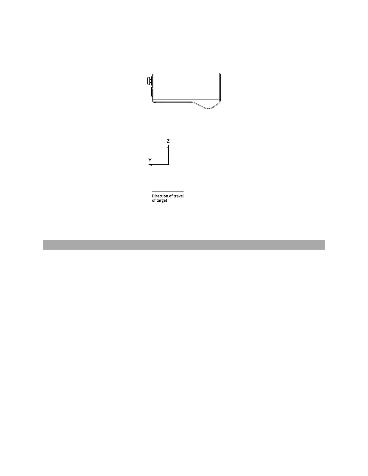
The Y axis represents the relative position of the part in the direction of travel. Y position increases as the
object moves forward (increasing encoder position). The image below represents a left-handed
coordinate system.
Gocator 2130/2330 sensor
The mounting direction, relative to the direction of travel, can be set in Gocator using either the Normal
or Reverse layout. For more information, see Layout on page 96.
System Coordinates
Aligning sensors adjusts the coordinate system in relation to sensor coordinates, resulting in system
coordinates (for more information on sensor coordinates, see Sensor Coordinates on the previous page).
For more information on aligning sensors, see Alignment on page 138.
The adjustments resulting from alignment are called transformations (offsets along the axes and
rotations around the axes). Transformations are displayed in the Sensor panel on the Scan page. For
more information on transformations in the web interface, see Transformations on page 128.
System coordinates are aligned so that the system X axis is parallel to the alignment target surface. The
system Z origin is set to the base of the alignment target object. In both cases, alignment determines the
offsets in X and Z.
Alignment is used with a single sensor to compensate for mounting misalignment and to set a zero
reference, such as a conveyor belt surface.
 Loading...