Gocator Line Profile Sensors: User Manual
How Gocator Works • 60
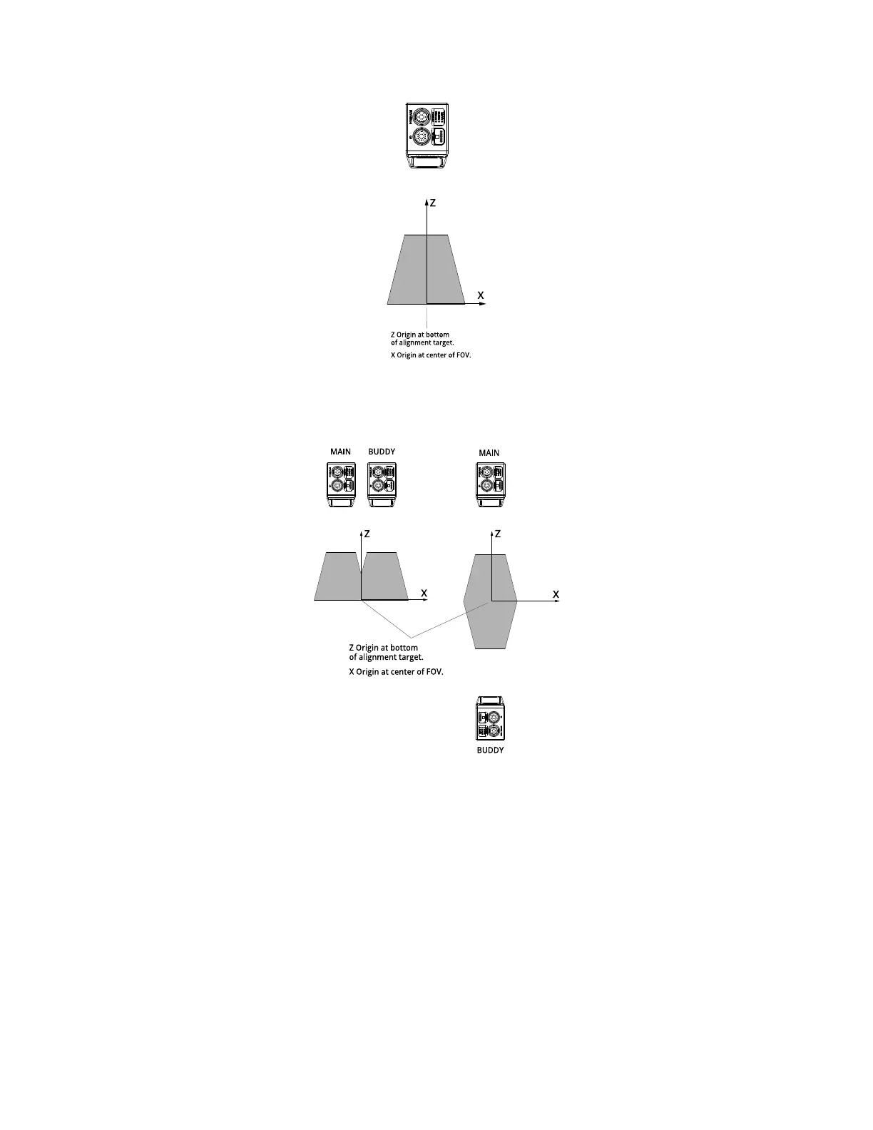
Gocator 2130/2330 sensor
Additionally, in multi-sensor systems, alignment sets a common coordinate system. That is, scan data
and measurements from the sensors are expressed in a unified coordinate system.
Gocator 2130/2330 sensors
Alignment can also determine offsets along the Yaxis. This allows setting up a staggered layout in multi-
sensor systems. This is especially useful in side-by-side mounting scenarios, as it provides full coverage
for models such as Gocator 2410 and Gocator 2420.
As with sensor coordinates, in system coordinates, Y position increases as the object moves forward
(increasing encoder position).
Alignment also determines the Y Angle (angle on the X–Z plane, around the Yaxis) needed to align sensor
data. This is also sometimes called roll correction.
 Loading...