Gocator Line Profile Sensors: User Manual
Gocator Web Interface • 165
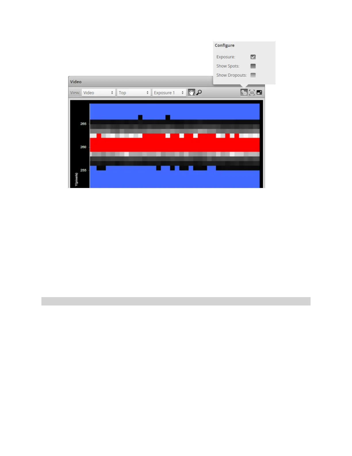
The Exposure setting uses the following colors:
l Blue: Indicates background pixels ignored by the sensor.
l Red: Indicates saturated pixels.
Correct tuning of exposure depends on the reflective properties of the target material and on the
requirements of the application. Settings should be carefully evaluated for each application, but often a
good starting point is to set the exposure so that there are 2 to 3 red pixels in the center of the laser line.
To display an overlay:
1. Go to the Scan page and choose Video mode in the Scan Mode panel.
2. Check Exposure at the top of the data viewer.
Spots and Dropouts
Various settings can affect how the Material settings behave. In Video mode, you can examine how the
Material settings are affected. To do this, in Video mode, check the Show Spots option at the top of
the data viewer to overlay a representation of the spots in the data viewer.
In the image below, the white and gray squares represent the laser line as it appears on the camera
sensor. Spots (which represent the center of the laser line on the camera sensor for each column)are
displayed as red "x"symbols. Dropouts (where no spot is detected on the camera sensor in a given
column)are depicted at the upper edge of the data viewer as yellow dots.
 Loading...

