Gocator Line Profile Sensors: User Manual
Gocator Web Interface • 392
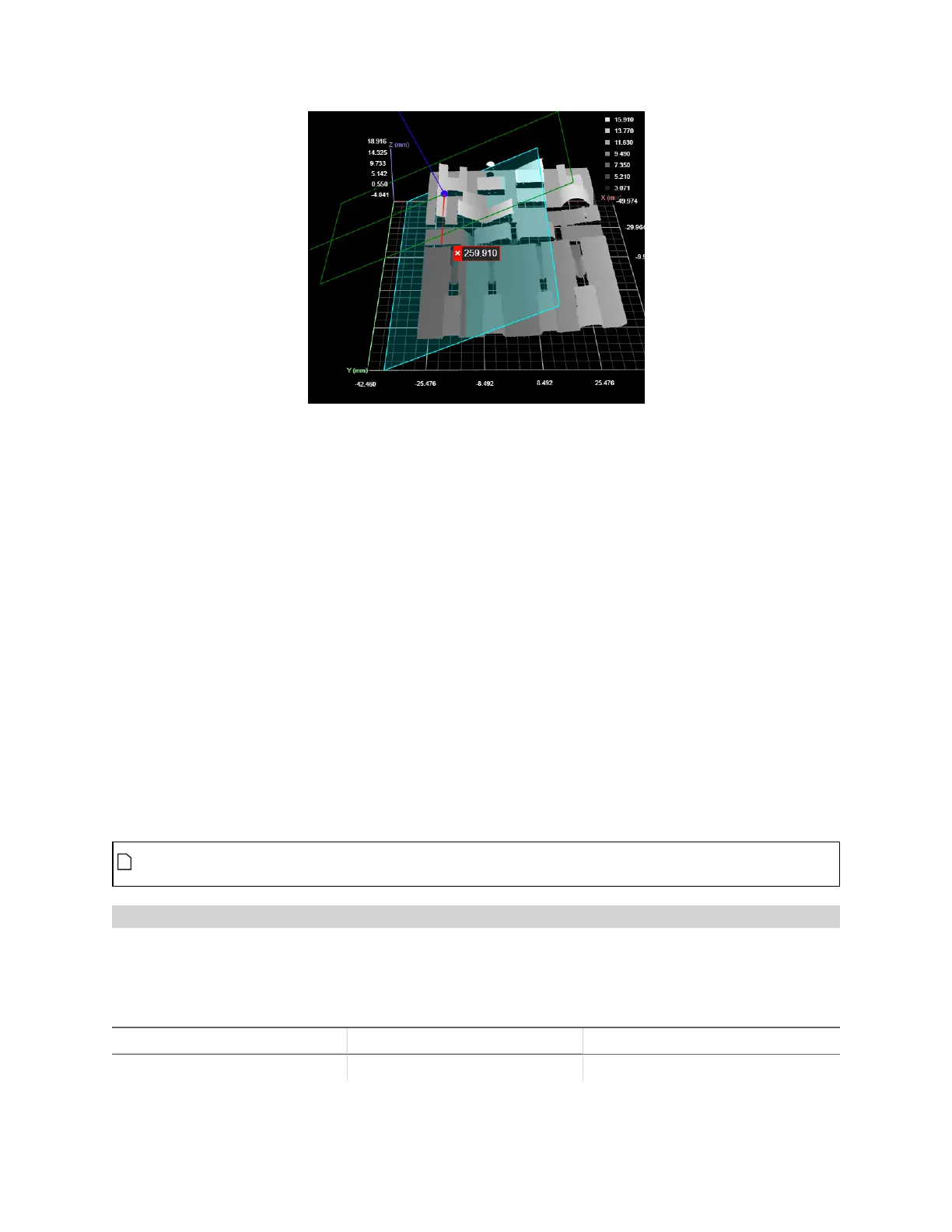
A Surface Transform tool using all three types of geometric feature inputs.
The data viewer is set to display the input surface data with an overlay of the transformed coordinate system.
In the data viewer, the following is displayed:
X, Y, and Zaxes
The transformed axes are represented above by the red, green, and blue lines intersecting on the surface
data above. Note how these are rotated with respect to the original coordinate system (the background
grid, axes, and values along the axes).
Origin
The new origin is represented by the dark blue dot at the intersection of the transformed axes.
Plane
The new plane is represented by the cyan rectangle.
Bounding box containing the transformed surface
The bounding box that indicates where the transformed data is in relation to the original coordinate
system.
To switch between the original and transformed data, choose Surface or Tool in the first drop-
down above the data viewer, respectively.
Combinations of geometric feature inputs and results
The Surface Transform tool accepts all combinations of input geometric features (plane, line, and point).
For details and examples of each, see the following sections.
Plane
New Z=0 XY Plane New X Axis New Origin
Matches the input plane. Parallel to the old X axis. Old origin projected to plane.
 Loading...