Gocator Line Profile Sensors: User Manual
Getting Started • 23
Hardware Overview
The following sections describe Gocator and its associated hardware.
Gocator Sensor
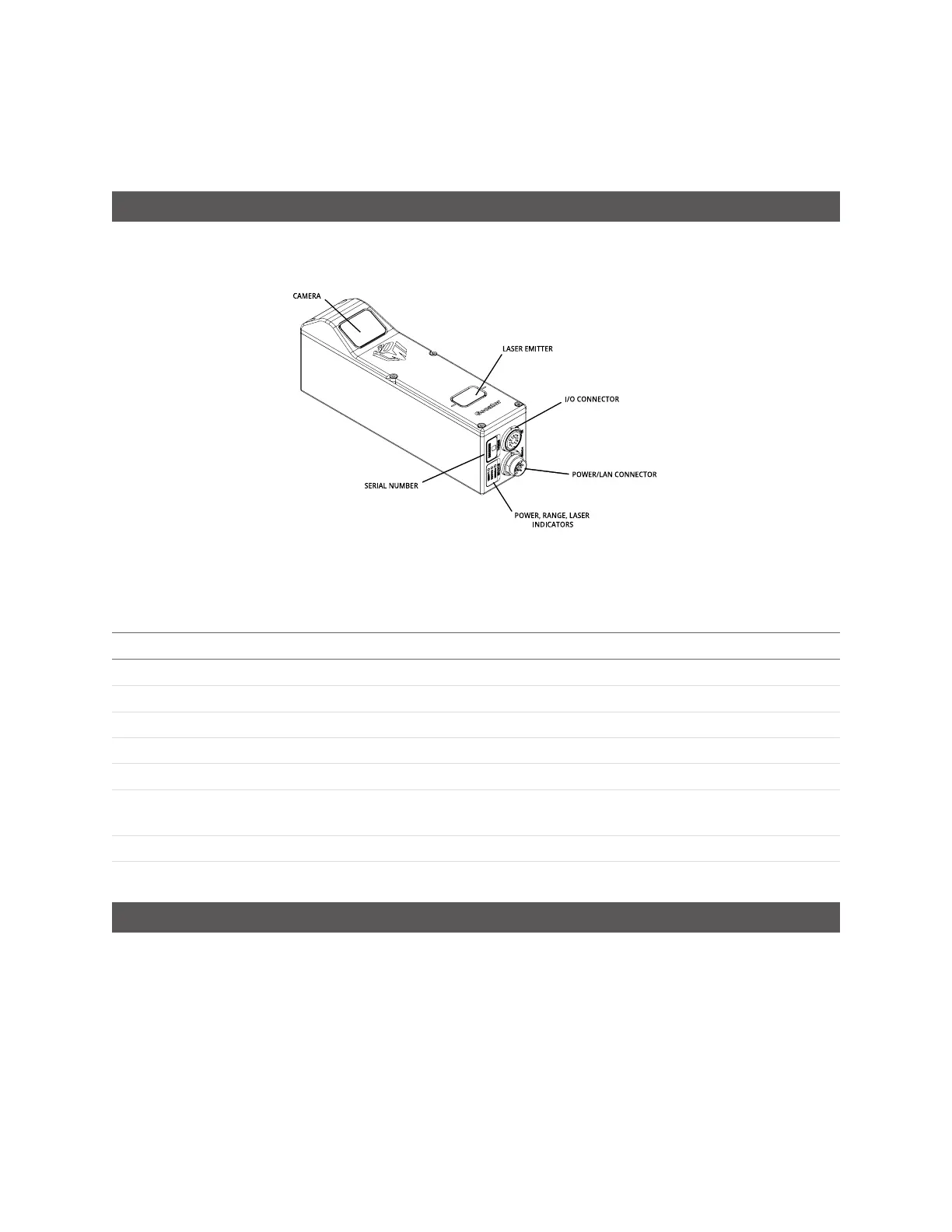
Gocator 2140 / 2340
Item Description
Camera Observes laser light reflected from target surfaces.
Laser Emitter Emits structured light for laser profiling.
I/O Connector Accepts input and output signals.
Power / LAN Connector Accepts power and laser safety signals and connects to 1000 Mbit/s Ethernet network.
Power Indicator Illuminates when power is applied (blue).
Range Indicator Illuminates when camera detects laser light and is within the sensor's measurement
range (green).
Laser Indicator Illuminates when laser safety input is active (amber).
Serial Number Unique sensor serial number.
Gocator Cordsets
Gocator sensors use two types of cordsets:the Power & Ethernet cordset and the I/Ocordset.
The Power & Ethernet cordset provides power, laser safety interlock to the sensor. It is also used for
sensor communication via 1000 Mbit/s Ethernet with a standard RJ45 connector. The Master version of
the Power & Ethernet cordset provides direct connection between the sensor and a Master network
controller, excluding Master 100 (for more information, see Master Network Controllers on page 773).
 Loading...

