Gocator Line Profile Sensors: User Manual
Gocator Web Interface • 173
When in the Scan page, selecting a panel (e.g., Sensor or Alignment panel) automatically sets the
display to the most appropriate display view.
To manually select the display view in the Scan page:
1. Go to the Scan page.
2. Choose Surface mode in the Scan Mode panel.
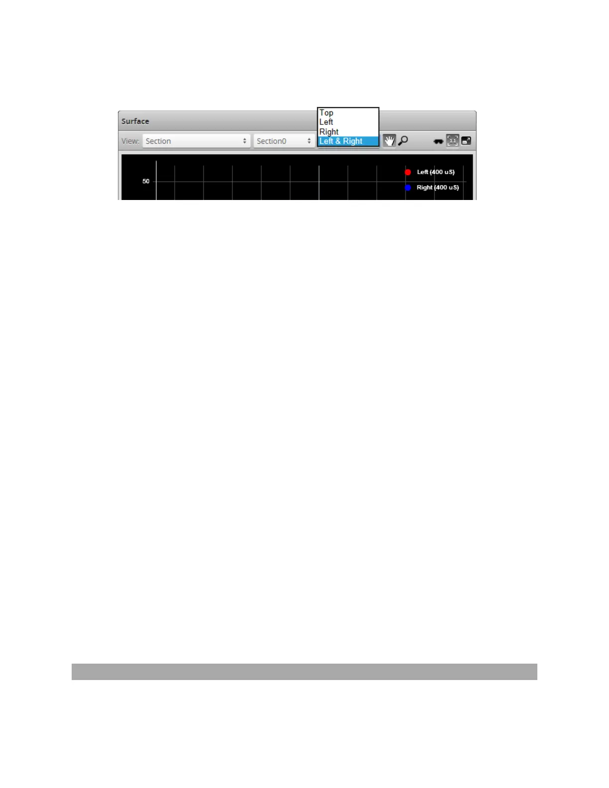
3. Just above the data viewer, choose Section in the View drop-down.
The view from an individual sensor or the combined view of two sensors can be selected from the drop-
down list at the top of the data viewer.
Top: View from a single sensor, from the top sensor in an opposite-layout dual-sensor system, or the
combined view of sensors that have been aligned to use a common coordinate system.
Bottom: View from the bottom sensor in an opposite-layout dual-sensor system.
Left: View from the left sensor in a dual-sensor system.
Right: View from the right sensor in a dual-sensor system.
Left &Right: Views from both sensors, displayed at the same time in the data viewer, using the
coordinate systems of each sensor.
1. Go to the Scan page.
2. Choose Surface mode in the Scan Mode panel.
3. Just above the data viewer, choose Section in the View drop-down.
The view from an individual sensor or the combined view of two sensors can be selected from the drop-
down list at the top of the data viewer.
Top: View from a single sensor, from the top sensor in an opposite-layout dual-sensor system, or the
combined view of sensors that have been aligned to use a common coordinate system.
Bottom: View from the bottom sensor in an opposite-layout dual-sensor system.
Left: View from the left sensor in a dual-sensor system.
Right: View from the right sensor in a dual-sensor system.
Left &Right: Views from both sensors, displayed at the same time in the data viewer, using the
coordinate systems of each sensor.
In the Measure page, the view of the display is set to the profile source of the selected measurement
tool.
Region Definition
Regions, such as an active area or a measurement region, can be graphically set up using the data viewer.
 Loading...