Gocator Line Profile Sensors: User Manual
How Gocator Works • 65
When uniform spacing is enabled, in the Ethernet output, only the range values (Z) are reported.
The X positions can be reconstructed through the array index at the receiving end (the client).
For more information on Ethernet output, see Ethernet Output on page 434.
For information on enabling uniform spacing, see Scan Modes on page 116.
Data Generation and Processing
After scanning a target, Gocator can process the scan data to allow the use of more sophisticated
measurement tools. This section describes the following concepts:
l Surface generation
l Part detection
l Sectioning
Surface Generation
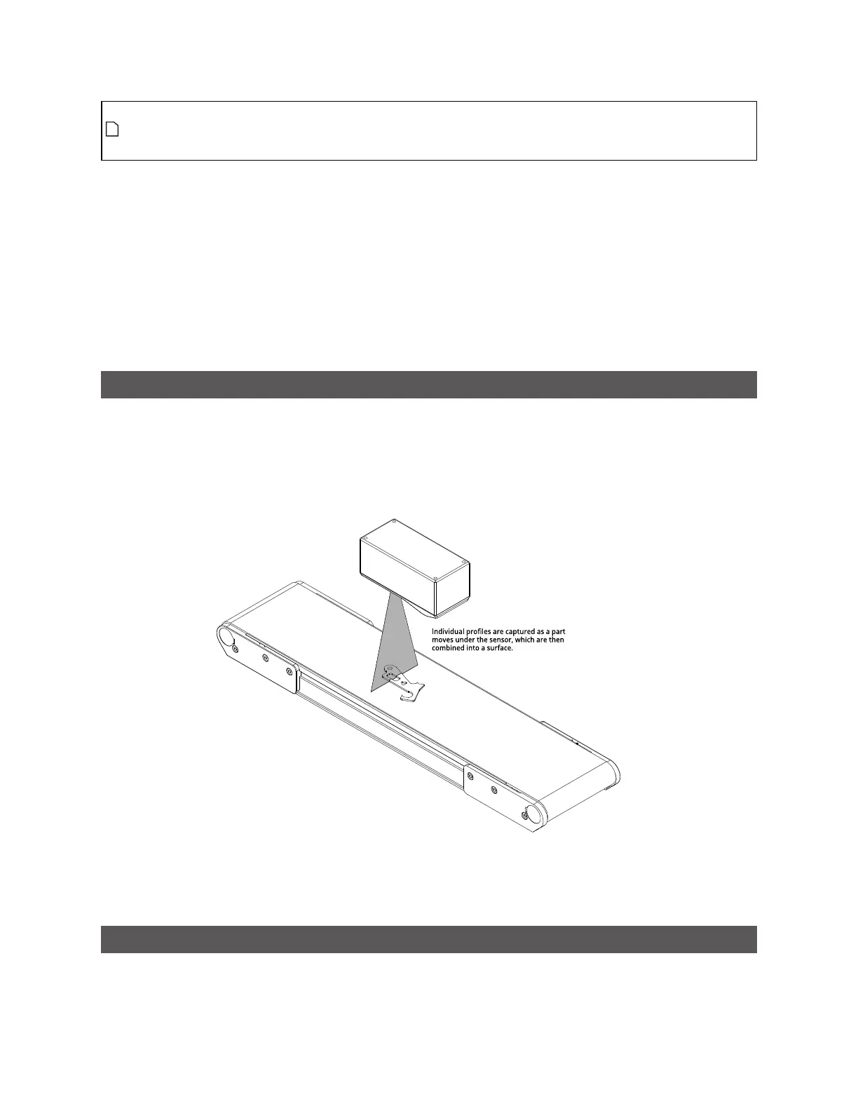
Gocator laser profile sensors create a single profile with each exposure. These sensors can combine a
series of profiles gathered as a target moves under the sensor to generate a height map, or surface, of
the entire target.
For more information, see Surface Generation on page 149.
Part Detection
After Gocator has generated a surface by combining single exposures into larger pieces of data, the
firmware can isolate discrete parts on a generated surface into separate scans representing parts.
 Loading...