Gocator Line Profile Sensors: User Manual
Getting Started • 25
Item Description
Safety Switch Toggles safety signal provided to the sensors [O= off, I= on]. This switch must be set to
on in order to scan with laser-based sensors.
Trigger Signals a digital input trigger to the Gocator.
Encoder Accepts encoder A, B and Z signals.
Digital Output Provides digital output.
See Master 100 on page 773 for pinout details.
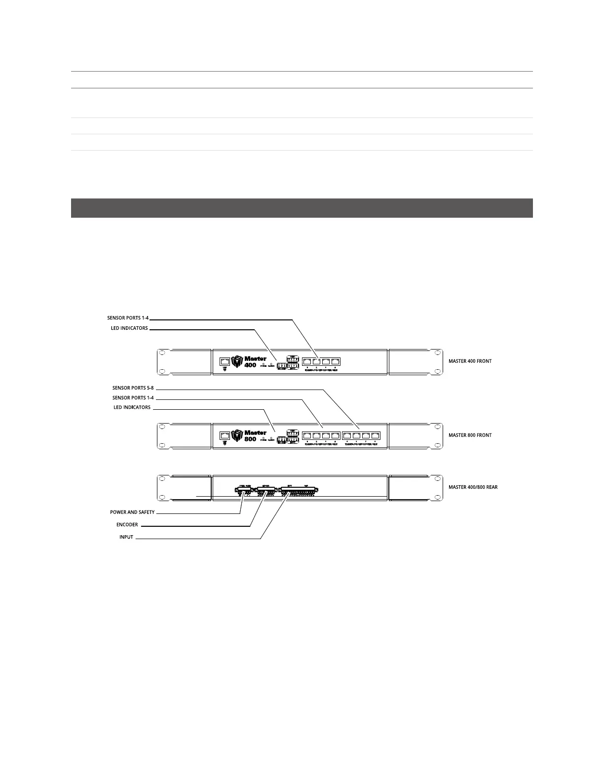
Master 400 / 800 / 1200 / 2400
The Master 400, 800, 1200, and 2400 network controllers let you connect more than two sensors:
l Master 400: accepts four sensors
l Master 800 accepts eight sensors
l Master 1200:accepts twelve sensors
l Master 2400:accepts twenty-four sensors
Master 400 and 800
 Loading...

