Gocator Line Profile Sensors: User Manual
Specifications • 771
four quadrature signals (A+/ A- /B+ / B-). Because Gocator reads each of the four quadrature
signals, you should choose an encoder accordingly, given the resolution required for your
application.
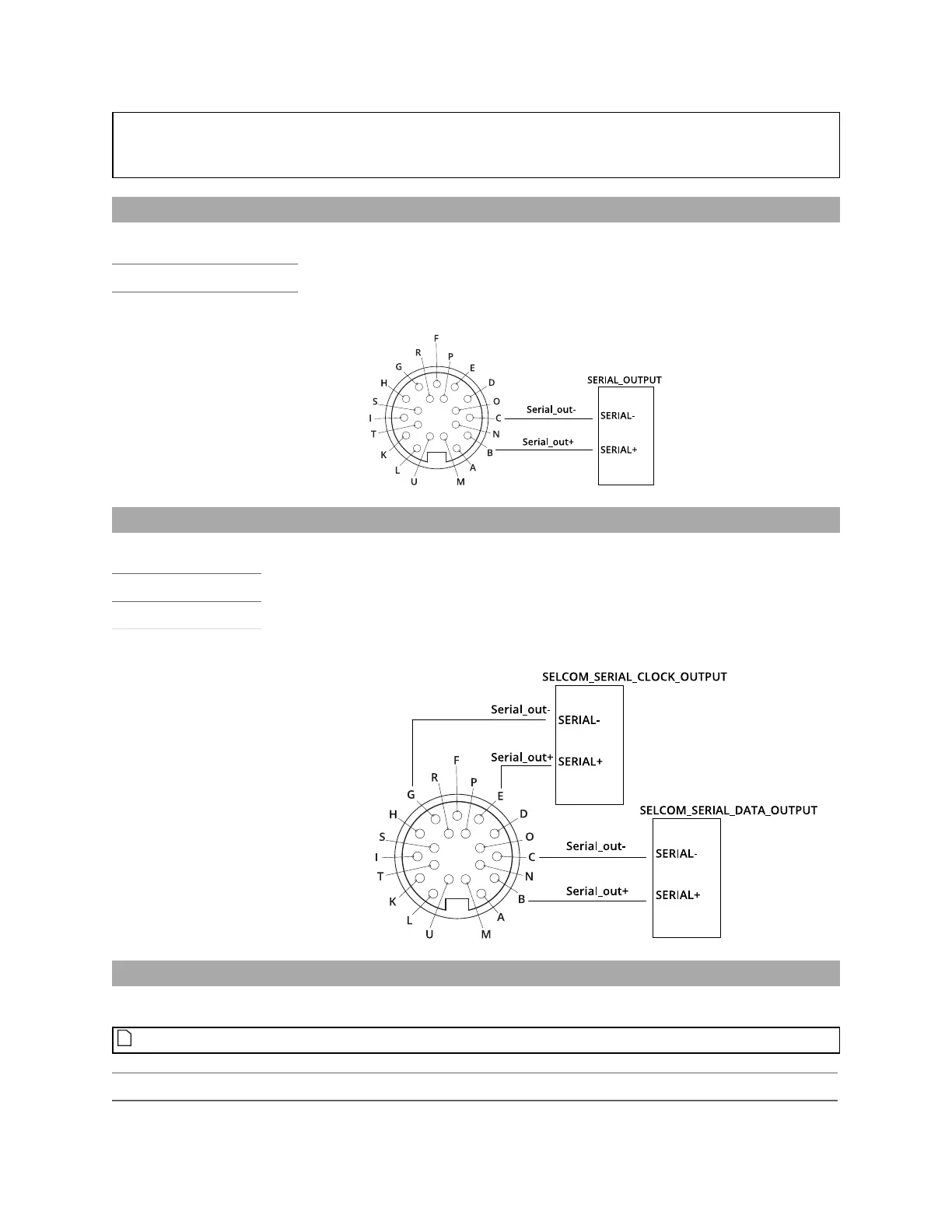
Serial Output
Serial RS-485 output is connected to Serial_out as shown below.
Function Pins
Serial_out B, C
Selcom Serial Output
Serial RS-485 output is connected to Serial_out and Serial_out2 as shown below.
Function Pins
Serial_out (data) B, C
Serial_out2 (clock) E, G
Analog Output
The Sensor I/O Connector defines one analog output interface: Analog_out.
You do not need to supply an external power source.
Function Pins Current Range
Analog_out P, F 4 – 20 mA
 Loading...

