Gocator Line Profile Sensors: User Manual
Gocator Web Interface • 354
Parameter Description
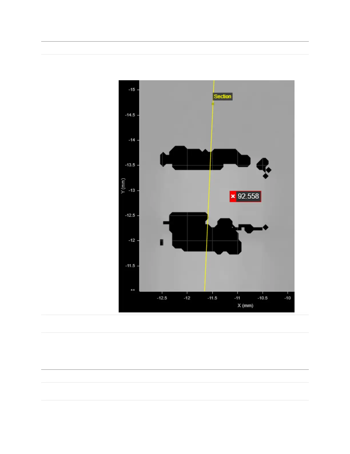
Show Detail Determines whether data points (in red)are displayed under the section in the data
viewer. If this setting is disabled, only the yellow line representing the defined section
is displayed.
Filters The filters that are applied to measurement values before they are output. For more
information, see Filters on page 209.
Decision The Max and Min settings define the range that determines whether the
measurement tool sends a pass or fail decision to the output. For more information,
see Decisions on page 208.
Anchor Description
X, Y, or Z Lets you choose the X, Y, or Z measurement of another tool
to use as a positional anchor for this tool.
Z angle Lets you choose the Z Angle measurement of another tool to
use as an angle anchor for this tool.
Anchoring
 Loading...