EasyManua.ls Logo

LSIS LSLV-S100 - Page 249

LSIS LSLV-S100
469 pages
To Next Page IconTo Next Page
To Previous Page IconTo Previous Page
Loading...
Learning Advanced Features
235
AO1: 0~10V / 4~20mA Output
Group
Code
Name
LCD Display
Parameter Setting
Setting Range
Unit
OU
01
Analog output1
AO1 Mode
0
Frequency
015
-
02
Analog output1 gain
AO1 Gain
100.0
-1000.0
1000.0
%
03
Analog output1 bias
AO1 Bias
0.0
-100.0100.0
%
04
Analog output1 filter
AO1 Filter
5
010000
ms
05
Analog constant output1
AO1
Const %
0.0
0.0100.0
%
06
Analog output1 monitor
AO1 Monitor
0.0
0.01000.0
%
AO2: 0~10V Output
Group
Code
Name
LCD Display
Parameter Setting
Setting Range
Unit
OU
07
Analog output1
AO2 Mode
0
Frequency
015
-
08
Analog output1 gain
AO2 Gain
100.0
-1000.0
1000.0
%
09
Analog output1 bias
AO2 Bias
0.0
-100.0100.0
%
10
Analog output1 filter
AO2 Filter
5
010000
ms
11
Analog constant output1
AO2
Const %
0.0
0.0100.0
%
12
Analog output1 monitor
AO2 Monitor
0.0
0.01000.0
%
Voltage and Current Analog Output Setting Details
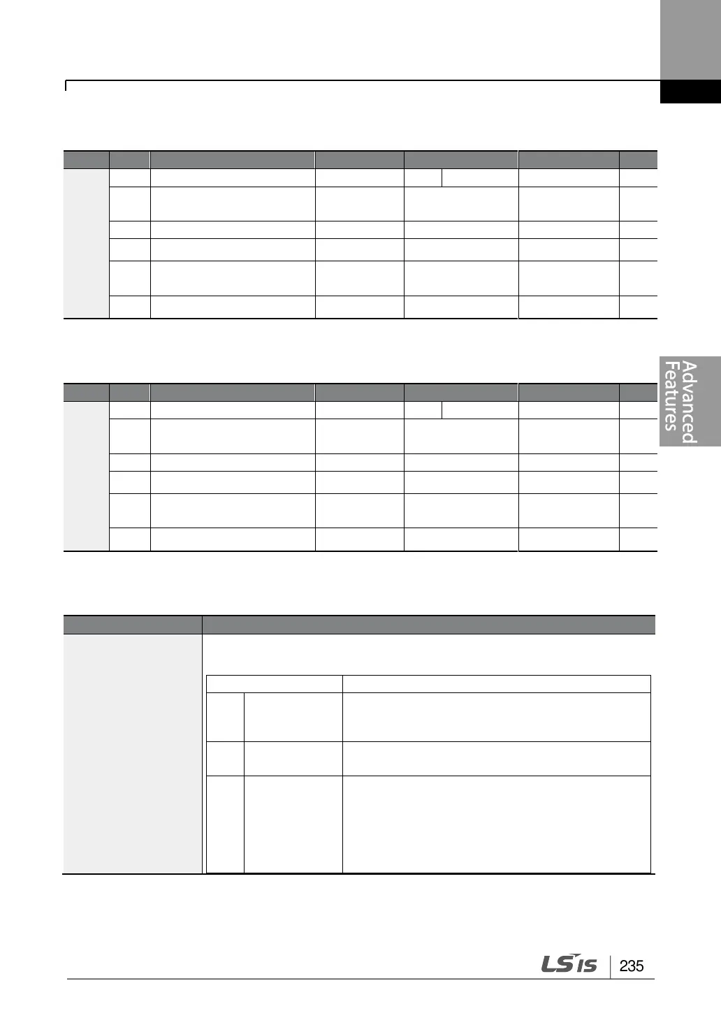
Code
Description
OU.01 AO1 Mode,
OU.07 AO2 Mode
Select a constant value for output. The following example for output
voltage setting.
Setting
Function
0
Frequency
Outputs operation frequency as a standard.
10V output is made from the frequency set at
dr.20(Max Freq)
1
Output
Current
10V output is made from 200% of inverter rated
current (heavy load).
2
Output
Voltage
Sets the outputs based on the inverter output
voltage. 10V output is made from a set voltage
in bA.15 (Rated V).
If 0V is set in bA.15, 200V/240V/400V models
output 10V based on the actual input voltage
(480V).

Table of Contents

Other manuals for LSIS LSLV-S100

Related product manuals