EasyManua.ls Logo

LSIS LSLV-S100 - Low Voltage Fault Trip

LSIS LSLV-S100
469 pages
To Next Page IconTo Next Page
To Previous Page IconTo Previous Page
Loading...
Learning Protection Features
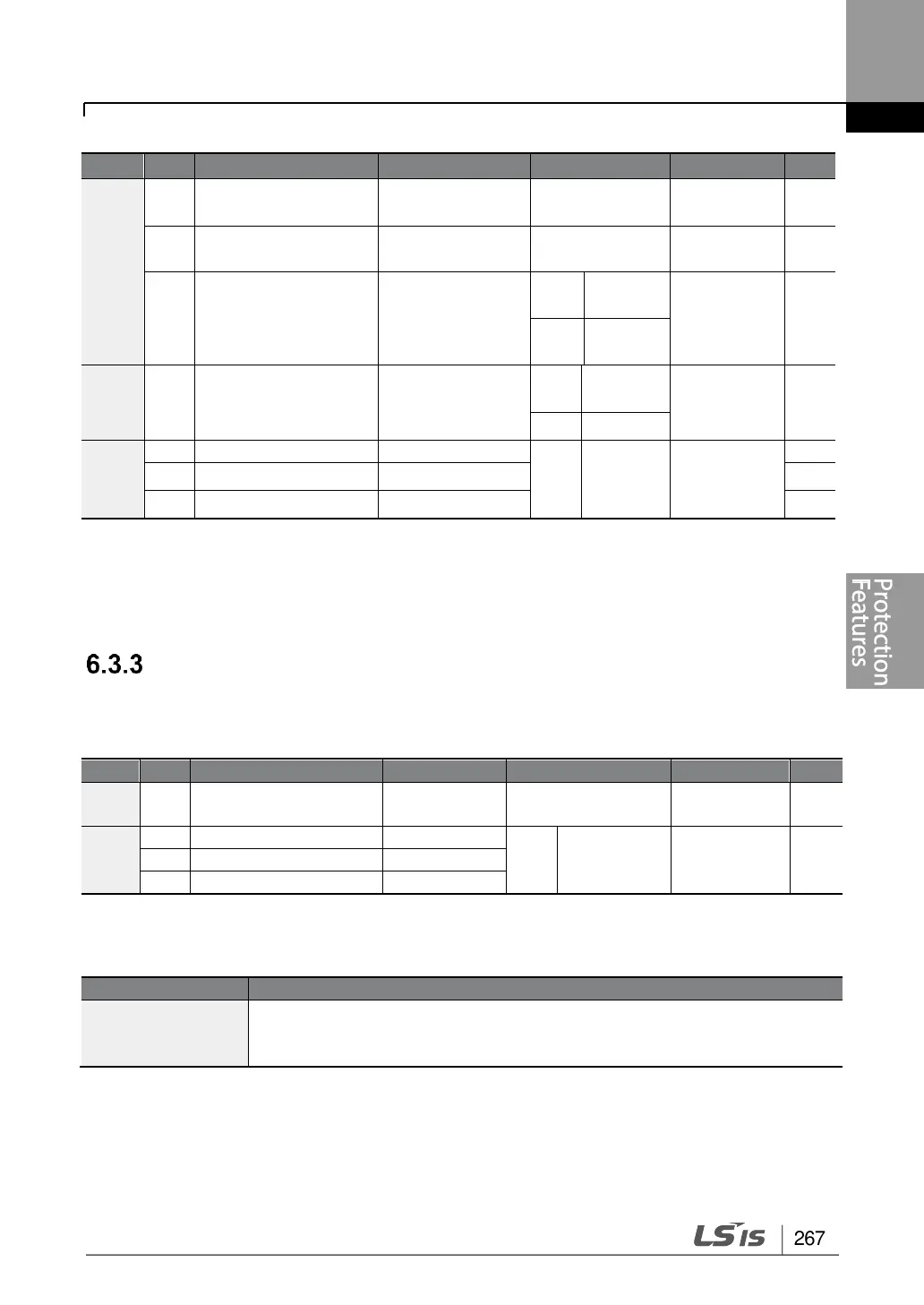
267
Group
Code
Name
LCD Display
Setting value
Setting
Range
Unit
Pr
86
Accumulated
percentof fan usage
FAN Time Perc
0.0
0.0-6553.5
%
87
Fan exchange
warning Level
FAN Exchange
level
90.0
0.0-100.0
%
88*
Initialize operation
time of cooling fans
FAN Time Rst
0
No
-
-
1
Yes
CNF
75**
Initialize operation
time of cooling fans
FAN Time Rst
0
No
-
-
1
Yes
OU
31
Multi-function relay 1
Relay 1
38
FAN
Exchang
e
-
32
Multi-function relay 2
Relay 2
33
Multi-function output 1
Q1 Define
* Available on keypad only.
** Available on LCD loader only.
Low Voltage Fault Trip
When inverter input power is lost and the internal DC link voltage drops below a certain voltage
level, the inverter stops output and a low voltage trip occurs.
Group
Code
Name
LCD Display
Parameter Setting
Setting range
Unit
Pr
81
Low voltage trip
decision delay time
LVT Delay
0.0
0-60
sec
OU
31
Multi-function relay 1
Relay 1
11
Low Voltage
-
32*
Multi-function relay 2
Relay 2
33
Multi-function output 1
Q1 Define
* Available for 30-75kW models only.
Low Voltage Fault Trip Setting Details
Code
Description
Pr.81 LVT Delay
If the multi-functional relay or terminal output is set to 11 (Low Voltage), a
low voltage trip condition arises. The relay or terminal output is on after the
trip delay time (Pr.81: LVT Delay).

Table of Contents

Other manuals for LSIS LSLV-S100

Related product manuals