Learning Protection Features
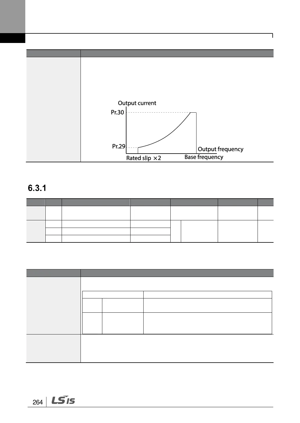
- At Pr.29, the under load rate is decided based on twice the operation
frequency of the motor’s rated slip speed (bA.12 Rated Slip).
- At Pr.30, the under load rate is decided based on the base frequency set
at dr.18 (Base Freq).An upper limit and lower limit is based on the
inverter’s rated current.
Fan Fault Detection
Cooling fan fault
selection
* Available for 30-75kW models only.
Fan Fault Detection Setting Details
Set the cooling fan fault mode.
The inverter output is blocked and the fan trip is
displayed when a cooling fan error is detected.
When OU.33 (Q1 Define) and OU.31 (Relay1)
are set to 8 (FAN Warning), the fan error signal
is output and the operation continues.
OU.32 Relay2,
OU.33 Q1 Define
When the code value is set to 8 (FAN Warning), the fan error signal is
output and operation continues. However, when the inverter inside
temperature rises above a certain level, output is blocked due to activation
of overheat protection.

 Loading...


