Learning Advanced Features
5.1 Operating with Auxiliary References
Frequency references can be configured with various calculated conditions that use the
main and auxiliary frequency references simultaneously. The main frequency reference is
used as the operating frequency, while auxiliary references are used to modify and fine-tune
the main reference.
Frequency reference
source
Auxiliary frequency
reference source
Auxiliary frequency
reference calculation
type
Auxiliary frequency
reference gain
Px terminal
configuration
The table above lists the available calculated conditions for the main and auxiliary
frequency references. Refer to the table to see how the calculations apply to an example
where the Frq code has been set to 0(Keypad-1), and the inverter is operating at a main
reference frequency of 30.00Hz. Signals at -10 – +10V are received at terminal V1, with the
reference gain set at 5%. In this example, the resulting frequency reference is fine-tuned
within the range of 27.00–33.00Hz [Codes In.01–16 must be set to the default values, and
In.06 (V1 Polarity), set to 1 (Bipolar)].
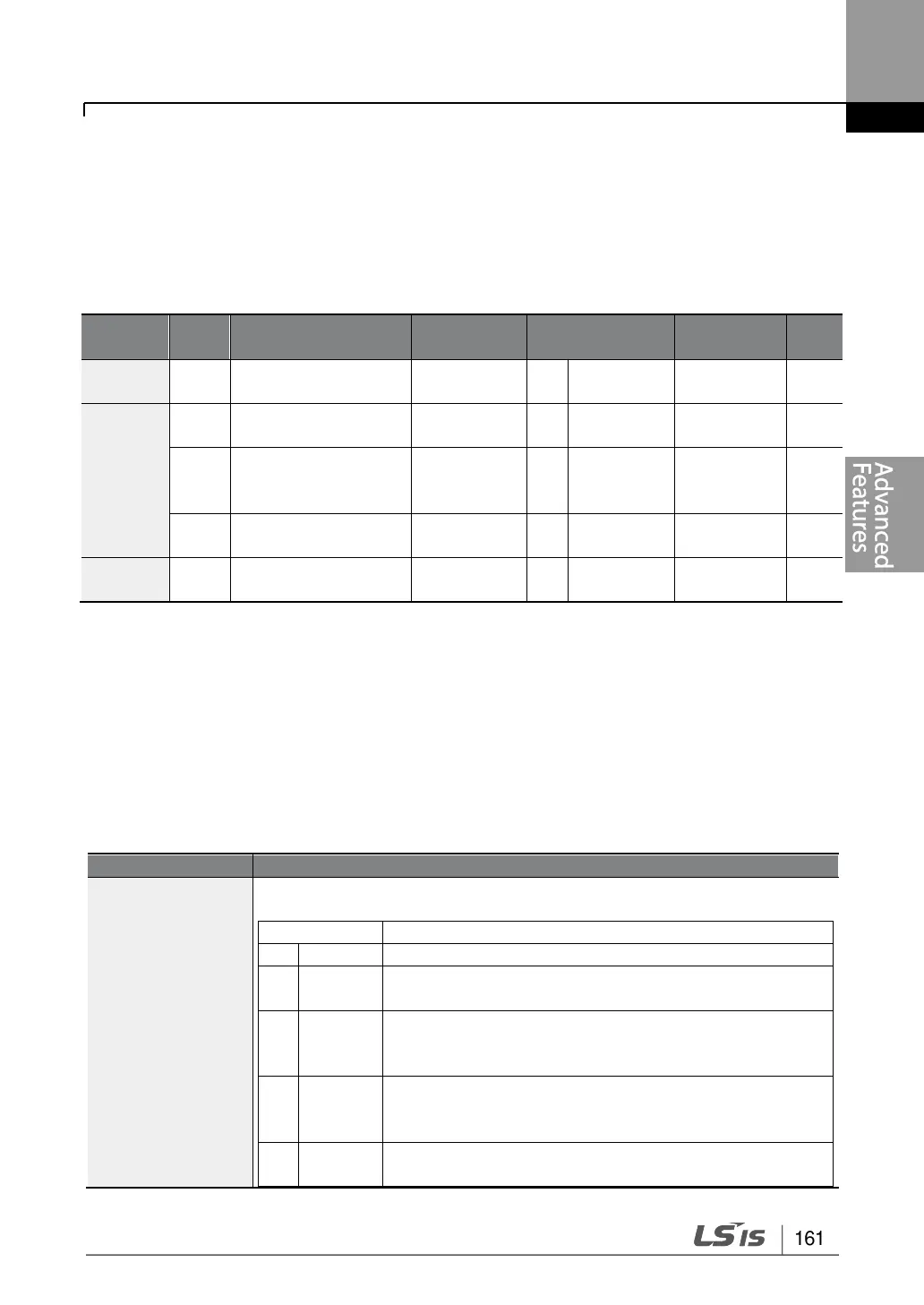
Auxiliary Reference Setting Details
Set the input type to be used for the auxiliary frequency reference.
Auxiliary frequency reference is disabled.
Sets the V1 (voltage) terminal at the control terminal
block as the source of auxiliary frequency reference.
Sets the V2 (voltage) terminal at the control terminal
block as the source of auxiliary frequency reference
(SW2 must be set to “voltage”).
Sets the I2 (current) terminal at the control terminal
block as the source of auxiliary frequency reference
(SW2 must be set to “current”).
Sets the TI (pulse) terminal at the control terminal block
as the source of auxiliary frequency reference.

 Loading...


