4 Learning Basic Features
This chapter describes the basic features of the S100 inverter. Parameter groups and
codes are described based on 0.4-22kW models. For 30-75kW models, refer to 3.1.5
Control Menuon page 64 Check the reference page in the table to see the detailed
description for each of the advanced features.
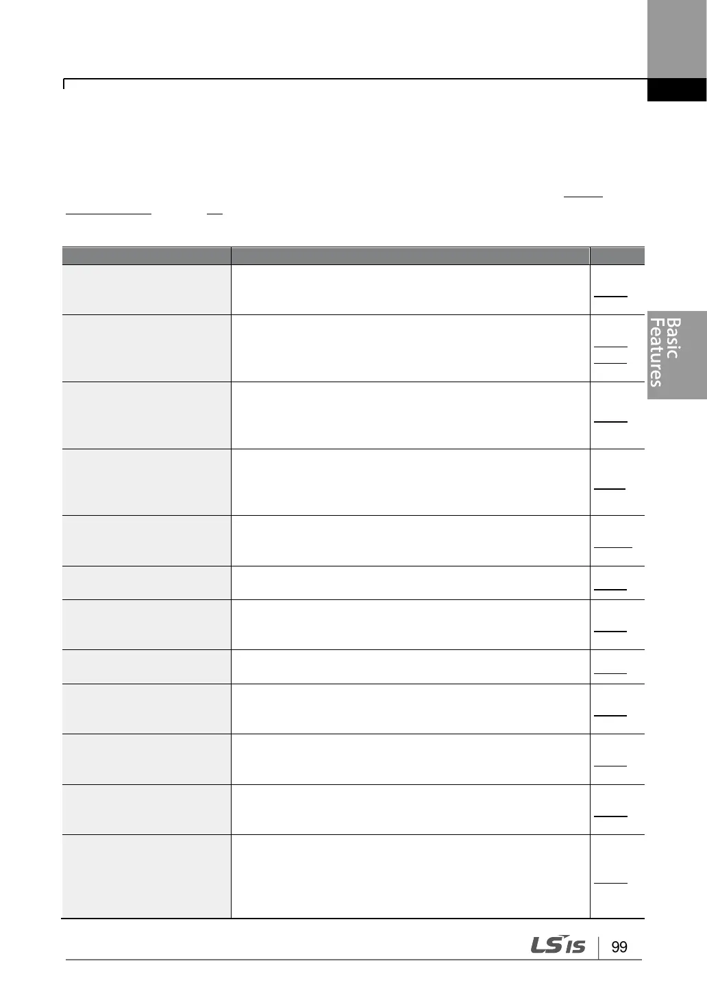
Frequency reference
source configuration for
the keypad
Configures the inverter to allow you to setup or modify
frequency reference using the Keypad.
Frequency reference
source configuration for
the terminal block (input
voltage)
Configures the inverter to allow input voltages at the
terminal block (V1, V2) and to setup or modify a frequency
reference.
Frequency reference
source configuration for
the terminal block (input
current)
Configures the inverter to allow input currents at the
terminal block (I2) and to setup or modify a frequency
reference.
Frequency reference
source configuration for
the terminal block (input
pulse)
Configures the inverter to allow input pulse at the terminal
block (TI) and to setup or modify a frequency reference.
Frequency reference
source configuration for
RS-485 communication
Configures the inverter to allow communication signals
from upper level controllers, such as PLCs or PCs, and to
setup or modify a frequency reference.
Frequency control using
analog inputs
Enables the user to hold a frequency using analog inputs
at terminals.
Motor operation display
options
Configures the display of motor operation values. Motor
operation is displayed either in frequency (Hz) or speed
(rpm).
Multi-step speed
(frequency) configuration
Configures multi-step frequency operations by receiving
an input at the terminals defined for each step frequency.
Command source
configuration for keypad
buttons
Configures the inverter to allow the manual operation of
the [FWD], [REV] and [Stop] keys.
Command source
configuration for terminal
block inputs
Configures the inverter to accept inputs at the FX/RX
terminals.
Command source
configuration for RS-485
communication
Configures the inverter to accept communication signals
from upper level controllers, such as PLCs or PCs.
Local/remote switching via
the [ESC] key
Configures the inverter to switch between local and remote
operation modes when the [ESC] key is pressed.
When the inverter is operated using remote inputs (any
input other than one from the keypad), this configuration
can be used to perform maintenance on the inverter,

 Loading...


