EasyManua.ls Logo

LSIS LSLV-S100 - Page 122

LSIS LSLV-S100
469 pages
To Next Page IconTo Next Page
To Previous Page IconTo Previous Page
Loading...
108
Learning Basic Features
Group
Code
Name
LCD Display
Parameter
Setting
Setting Range
Unit
14
V1maximum input
voltage
V1- Volt x2
-10.00
-12.00 0.00V
V
15
V1 output at maximum
voltage (%)
V1- Perc y2
-100.00
-100.000.00%
%
Rotational Directions for Different Voltage Inputs
Command /
Voltage Input
Input voltage
0
10V
-10
0V
FWD
Forward
Reverse
REV
Reverse
Forward
-1010V Voltage Input Setting Details
Code
Description
In.12 V1- volt x1
In.15 V1- Perc y2
Sets the gradient level and off-set value of the output frequency in relation to
the input voltage. These codes are displayed only when In.06 is set to 1
(bipolar).
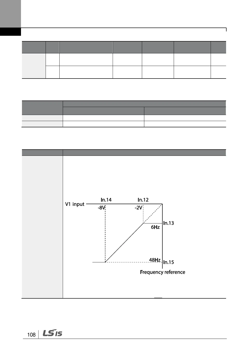
As an example, if the minimum input voltage (at V1) is set to -2 (V) with 10%
output ratio, and the maximum voltage is set to -8 (V) with 80% output ratio
respectively, the output frequency will vary within the range of 6 - 48 Hz.
[In.12 V1-volt X1In.15 V1 Perc y]
For details about the 0+10V analog inputs, refer to the code descriptions
In.08 V1 volt x1In.11 V1 Perc y2 on page 105.

Table of Contents

Other manuals for LSIS LSLV-S100

Related product manuals