Learning Protection Features
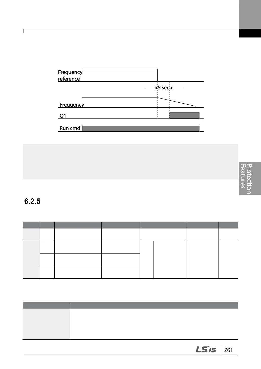
Set Pr.15 (Al Lost Level) to 1 (Below x 1), Pr.12 (Lost Cmd Mode) to 2 (Dec), and Pr.13
(Lost Cmd Time) to 5 sec. Then it operates as follows:
If speed command is lost while using communication options or the integrated RS-485
communication, the protection function operates after the command loss decision time set at
Pr.13 (Lost Cmd Time) is passed.
Dynamic Braking (DB) Resistor Configuration
For S100 series, the braking resistor circuit is integrated inside the inverter.
Braking resistor
configuration
Multi-function relay
1 item
Multi-function relay
2 item
Multi-function
output 1 item
* Available for 30-75kW models only.
Dynamic Breaking Resistor Setting Details
Set braking resistor configuration (%ED: Duty cycle). Braking resistor
configuration sets the rate at which the braking resistor operates for one
operation cycle. The maximum time for continuous braking is 15 sec and
the braking resistor signal is not output from the inverter after the 15 sec
period has expired. An example of braking resistor set up is as follows:

 Loading...


