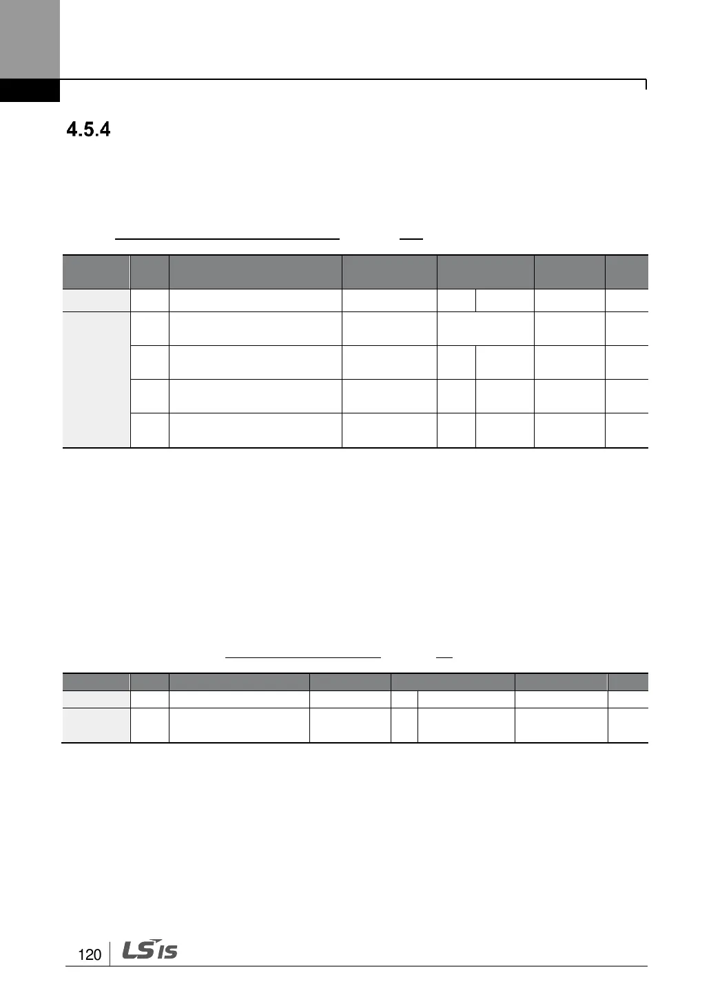
RS-485 Communication as a Command Input Device
Internal RS-485 communication can be selected as a command input device by setting the
drv (command source) code in the Operation group to 3(Int 485). This configuration uses
upper level controllers such as PCs or PLCs to control the inverter by transmitting and
receiving signals via the S+, S-, and Sg terminals at the terminal block. For more details,
refer to 7 RS-485 Communication Features on page 273.
Integrated communication
inverter ID
Integrated communication
protocol
Integrated communication
speed
Integrated communication
frame setup
* Displayed under DRV-06 on the LCD keypad.
4.6 Local/Remote Mode Switching
Local/remote switching is useful for checking the operation of an inverter or to perform an
inspection while retaining all parameter values. Also, in an emergency, it can also be used
to override control and operate the system manually using the keypad.
The [ESC] key is a programmable key that can be configured to carry out multiple functions.
For more details, refer to 3.2.4.2 30-75kW Modelson page 78.
* Displayed under DRV-06 on the LCD keypad.

 Loading...


