206
Using Intelligent Output Terminals Section 4-6
4-6-9 Alarm Signal
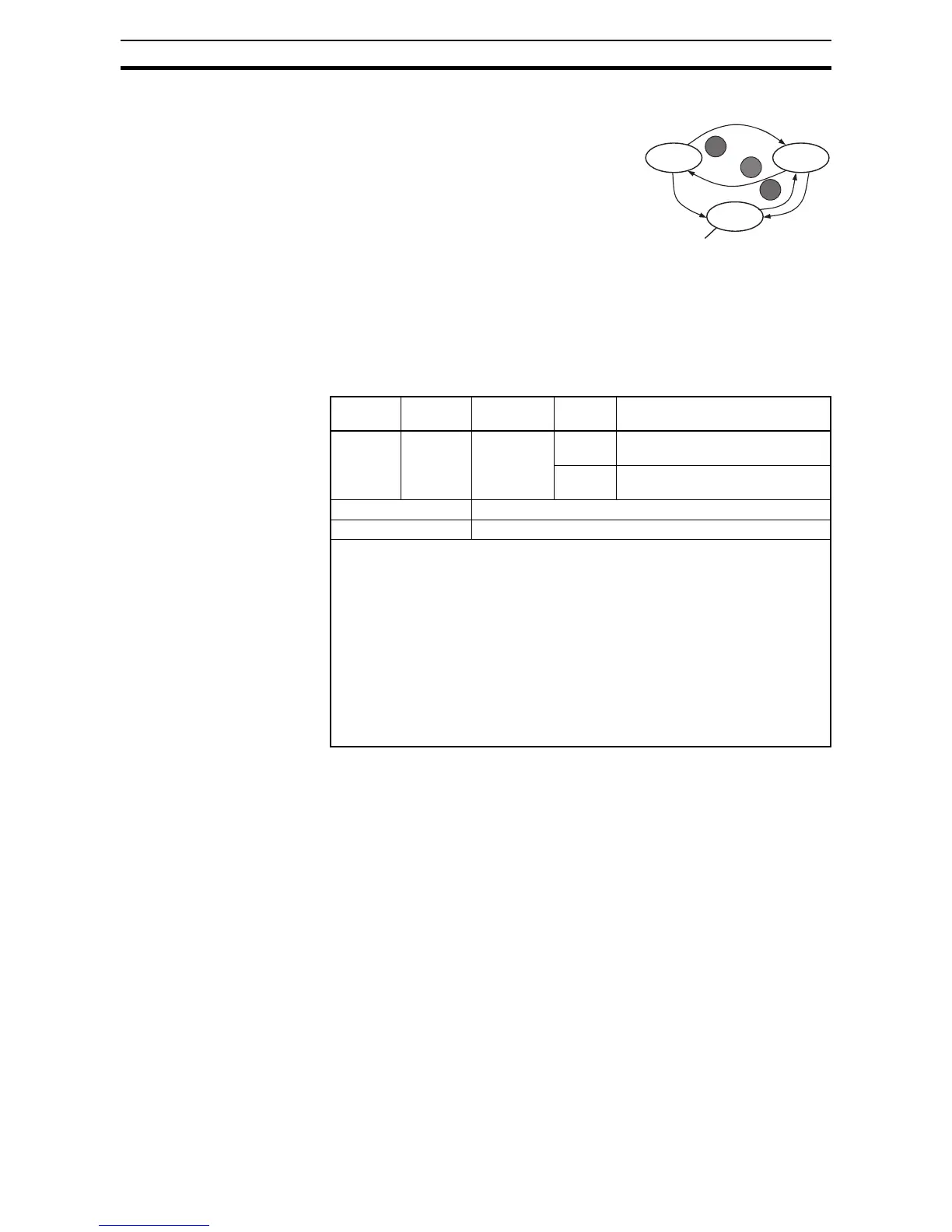
The inverter alarm signal is active when a
fault has occurred and it is in the Trip Mode
(refer to the diagram at right). When the fault
is cleared the alarm signal becomes inactive.
We must make a distinction between the
alarm signal AL and the alarm relay contacts
[AL0], [AL1] and [AL2]. The signal AL is a
logic function, which you can assign to the
open collector output terminals [11], [12], or
the relay outputs.
The most common (and default) use of the
relay is for AL, thus the labeling of its terminals. Use an open collector output
(terminal [11] or [12]) for a low-current logic signal interface or to energize a
small relay (50 mA maximum). Use the relay output to interface to higher volt-
age and current devices (10 mA minimum).
Option
Code
Terminal
Symbol
Function
Name
State Description
05 AL Alarm Sig-
nal
ON when an alarm signal has occurred
and has not been cleared
OFF when no alarm has occurred since
the last clearing of alarm(s)
Valid for inputs: 11, 12, AL0 - AL2
Required settings: C031, C032, C036
Notes:
• By default, the relay is configured as normally closed (C036=01). Refer to the next
page for an explanation.
• In the default relay configuration, an inverter power loss turns ON the alarm output.
the alarm signal remains ON as long as the external control circuit has power.
• When the relay output is set to normally closed, a time delay of less than 2 seconds
occurs after powerup before the contact is closed.
• Terminals [11] and [12] are open collector outputs, so the electric specifications of
[AL] are different from the contact output terminals [AL0], [AL1], [AL2].
• This signal output has the delay time (300 ms nominal) from the fault alarm output.
• The relay contact specifications are in 4-3 Control Logic Signal Specifications on
page 169. The contact diagrams for different conditions are on the next page.
Run Stop
RUN
STOP
RESET
Trip
STOP
RESET
Fault
Fault