43
Step-by-Step Basic Installation Section 2-3
2-3-12 Wire the Inverter Output to Motor
Step 4 The process of motor selection is beyond the scope of this manual. However,
it must be an AC induction motor with three phases. It should also come with a
chassis ground lug. If the motor does not have three power input leads, stop
the installation and verify the motor type. Other guidelines for wiring the motor
include:
• Use an inverter-grade motor for maximum motor life (1600 V insulation).
• For standard motors, use the AC reactor accessory if the wiring between
the inverter and motor exceeds 10 meters in length.
Simply connect the motor to the terminals [U/T1], [V/T2], and [W/T3] as
shown in page 38 to page 41. This is a good time to connect the chassis
ground lug on the drive as well. The motor chassis ground must also connect
to the same point. Use a star ground (single-point) arrangement, and never
daisy-chain the grounds (point-to-point).
• Check the mechanical integrity of each wire crimp and terminal connec-
tion.
• Replace the housing partition that covers access to the power connec-
tions.
Special care to be taken when motor is connected through long wires
2-3-13 Ground Terminal
To prevent electric shock, be sure to ground the Inverter and the motor.
The 200 V class should be connected to the ground terminal under Class D
grounding conditions (conventional Class 3 grounding conditions: 100 Ω or
less ground resistance), The 400 V class should be connected to the ground
terminal under Class C grounding conditions (conventional special Class 3
grounding conditions: 10 Ω or less ground resistance).
For the ground cable, use the compatible cable or a cable with a larger diame-
ter. Make the cable length as short as possible.
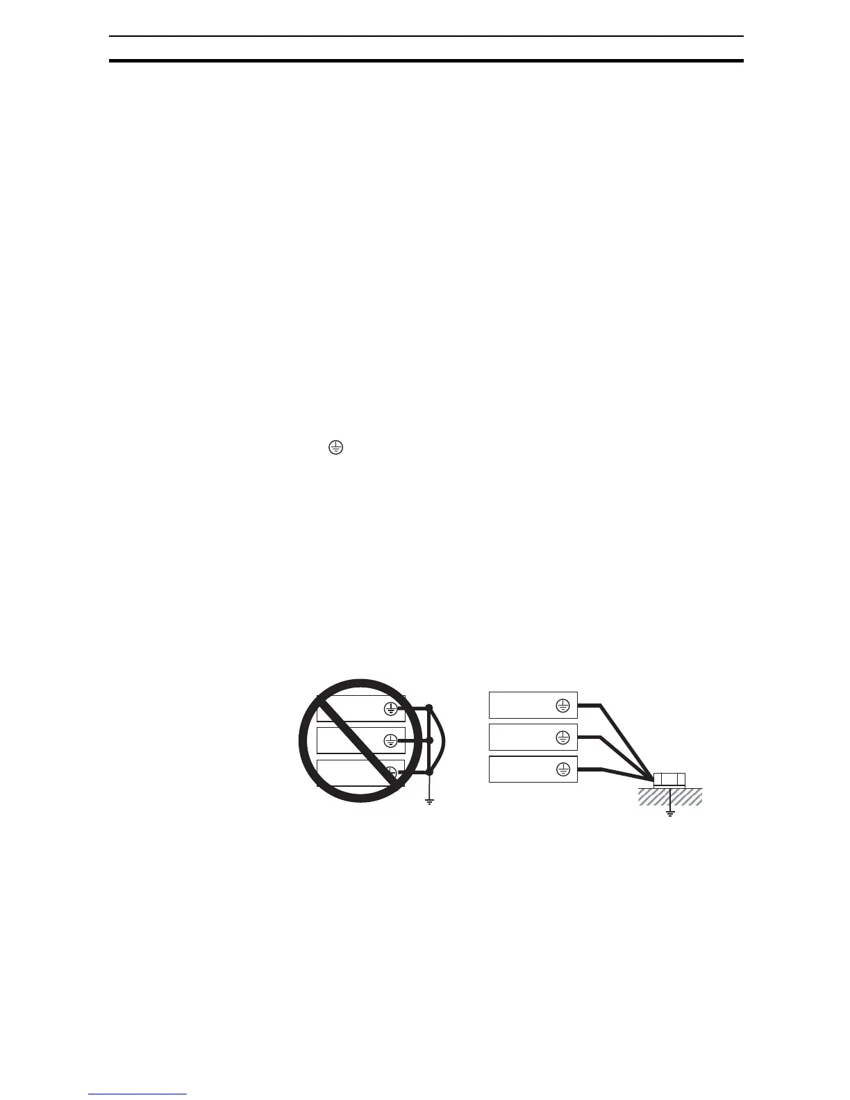
When several Inverters are connected, the ground cable must not be con-
nected across several Inverters, and must not be looped. Otherwise, the
Inverter and surrounding control machines may malfunction.
2-3-14 Logic Control Wiring
After completing the initial installation and powerup test in this chapter, you
may need to wire the logic signal connector for your application. For new
inverter users/applications, we highly recommend that you first complete the
powerup test in this chapter without adding any logic control wiring. As a quick
reference here is included the control connection diagram. But for more
details about inputs and outputs configuration, please check SECTION 4
Operations and Monitoring.
+PXGTVGT
+PXGTVGT
+PXGTVGT
+PXGTVGT
+PXGTVGT
+PXGTVGT
;QWTITQWPFDQNV