98
"A" Group: Standard Functions Section 3-5
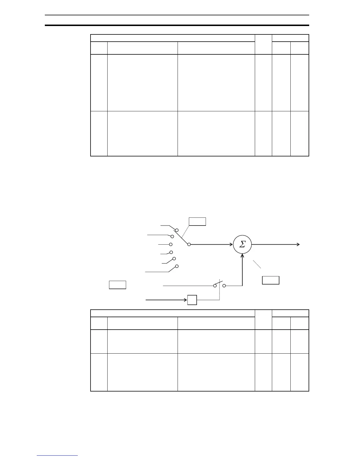
Add Frequency - The inverter can add or subtract on offset value to the out-
put frequency setting which is specified by A001 (will work with any of the five
possible sources). The ADD Frequency is a value you can store in parameter
A145. the ADD Frequency is summed with or subtracted from the output fre-
quency setting only when the [ADD] terminal is ON. Function A146 selects
whether to add or subtract. By configuring an intelligent input as the [ADD] ter-
minal, your application can selectively apply the fixed value in A145 to offset
(positively or negatively) the inverter output frequency in real time.
Input Range Settings - The parameters in the following table adjust the input
characteristics of the VR (POT meter on external operator) input. When using
A142 B input select for calculate
function
Seven options:
00... Operator
01... VR
02... Terminal [O] input
03... Terminal [OI] input
04... RS485
05... Option
07... Pulse train input
8 03 –
A143 Calculation symbol Calculates a value based on the A
input source (A141 selects) and B
input source (A142 selects). Three
options:
00... ADD (A input + B input)
01... SUB (A input - B input)
02... MUL (A input * B input)
8 00 –
"A" Function Run
Mode
Edit
Defaults
Func.
Code
Name Description EU Units
Control terminal
Function F001 setting
ModBus network input
Calculate function output
+
A001
Frequency source setting
Output frequency setting
A145
ADD frequency
A146
ADD direction select
+/-
Intelligent input
[ADD]
Remote operator POT
Option board
"A" Function Run
Mode
Edit
Defaults
Func.
Code
Name Description EU Units
A145 ADD frequency An offset value that is applied to
the output frequency when the
[ADD] terminal is ON. Range is
0.0 to 400.0 Hz
*1
9 0.00 Hz
A146 ADD direction select Two options:
00... Plus (adds A145 value to the
output frequency setting)
01... Minus (subtracts A145 value
from the output frequency
setting)
8 00 –
*1
Up to 1000Hz for High frequency mode (d060 set to "2")