39
Step-by-Step Basic Installation Section 2-3
2-3-9 Inverter output terminal (U/T1, V/T2, W/T3)
For connection of the output terminal, use the compatible cable or a cable with
a larger section. Otherwise, the output voltage between the Inverter and the
motor may drop.
Do not mount a phase advance capacitor or surge absorber, because these
devices may cause the Inverter to trip or cause damage to the capacitor or
surge absorber.
If the cable length exceeds 20 m (particularly, with 400 V class), a surge volt-
age may be generated at the motor terminal depending on stray capacitance
or inductance of the cable, causing the motor to risk his isolation (depending
on motor isolation class and conditions).
To suppress surge voltage, output filters are recommended. From simple
choke and output dV/dt filters to sinus filters.
To connect several motors, provide a thermal protection relay for each, as the
inverter can not recognize how current is shared among the motors.
The RC value of each thermal relay should be 1.1 times larger than the motor
rated current.The relay may trip earlier depending on the cable length.In this
case, connect an AC reactor to the Inverter output.
2-3-10 DC Reactor Connection (+1, P/+2)
This terminal is used to connect the optional DC reactor.
By factory default, a shorting bar has been connected between terminals +1
and P/+2. Before connecting the DC reactor, remove this shorting bar.
The length of the DC reactor connection cable should be 5 m or shorter.
If the DC reactor is not being used, do not remove the shorting bar.
If you remove the shorting bar without connecting the DC reactor, no power is
supplied to the Inverter main circuit, disabling operation.
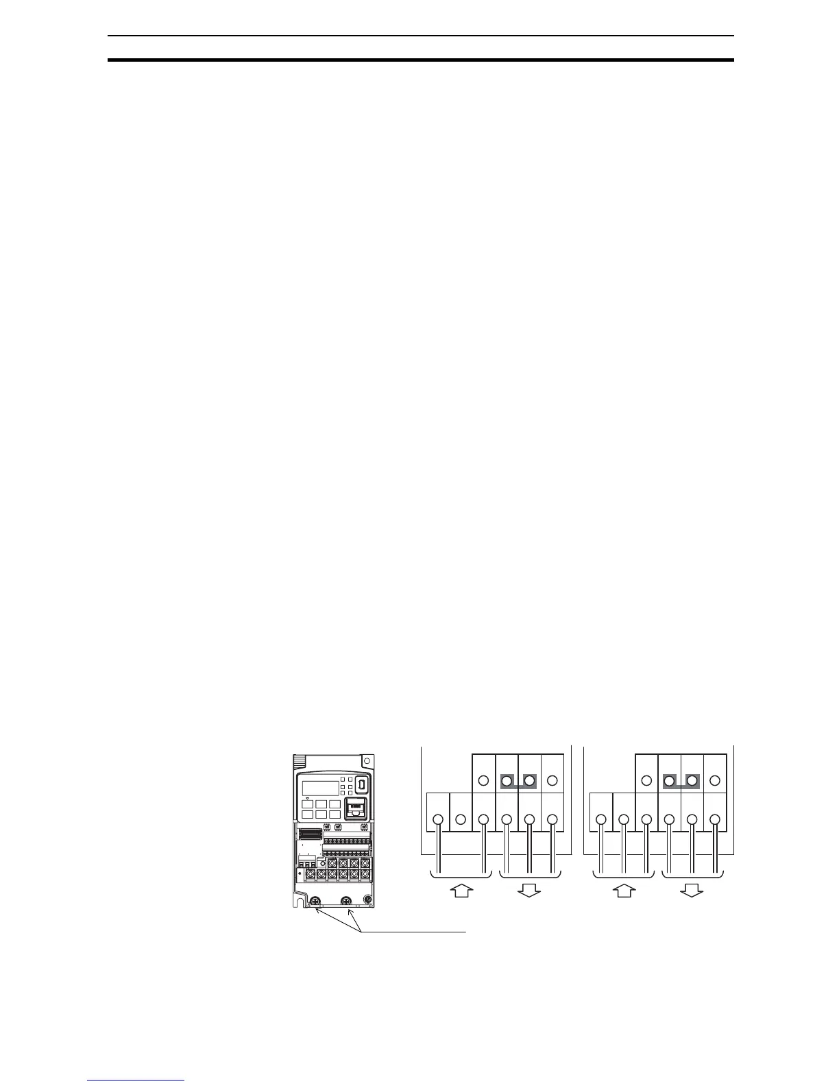
2-3-11 Power connections for each inverter size
Single-phase 200 V 0.1 to 0.4 kW
Three-phase 200 V 0.1 to 0.75 kW